
Face milling cutter advantages include high material-removal capacity, efficient production of broad flat surfaces, multiple cutting edges, replaceable inserts, flexible diameter options, and the ability to combine roughing and finishing strategies. Actual performance depends on cutter geometry, lead angle, insert grade, pitch, runout, machine power, workholding, and cutting data.
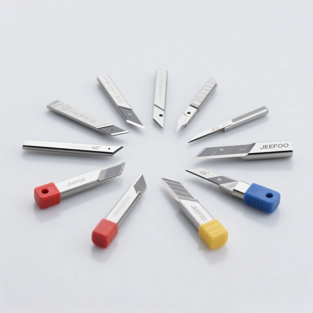
Face Milling Cutter Advantages: Quick Answer
A face mill uses teeth around the cutter body and often across part of its face to machine surfaces perpendicular to the spindle axis. Its large diameter covers a wide path, while multiple inserts share the cutting load. Indexable designs let users replace worn edges without discarding the entire cutter body.
Seven Main Advantages
- High productivity. Large diameters and multiple teeth can remove material across a broad surface in fewer passes.
- Flat-surface capability. Correct setup can produce consistent faces, shoulders, and datum surfaces.
- Replaceable cutting edges. Indexable inserts reduce tool-change cost and setup time.
- Grade flexibility. Insert carbide, coating, chipbreaker, and edge preparation can match the workpiece.
- Roughing and finishing options. Cutter pitch, lead angle, wiper inserts, and stock allowance can be optimized separately.
- Load distribution. Several teeth share the cut when runout and engagement are controlled.
- Scalable coverage. Cutter diameter can be selected for machine power, part width, and toolpath access.
Face Milling Vs Peripheral Milling
| Factor | Face milling | Peripheral milling |
|---|---|---|
| Main cutting orientation | Surface perpendicular to spindle axis | Surface parallel to cutter axis |
| Typical result | Broad flat face | Side wall, slot, or contour |
| Tool coverage | Large radial path | Depends on axial edge length |
| Common tool | Indexable face mill | End mill, side mill, or slab mill |
| Selection priority | Diameter, lead angle, pitch, inserts | Diameter, flute length, helix, reach |
How Lead Angle Changes Performance
A lower entering angle can spread the chip over a longer cutting edge and direct more force axially, while a 90-degree cutter supports square shoulders but directs more force radially. Round-insert and high-feed designs create different chip-thinning and load patterns. Choose the angle for part geometry, machine rigidity, spindle bearings, fixture strength, and insert recommendations.
How To Select A Face Mill
- Measure the surface. Match cutter diameter to part width and toolpath access.
- Check machine limits. Confirm spindle power, torque, taper, speed, and overhang.
- Choose lead angle. Balance shoulder access, radial force, axial force, and chip thinning.
- Select cutter pitch. Coarse pitch improves chip space; fine pitch adds teeth when power and stability permit.
- Match inserts. Choose grade, coating, geometry, corner, and wiper options for the material and finish.
- Plan engagement. Control entry, exit, cutter position, width of cut, and direction.
Surface Finish And Runout
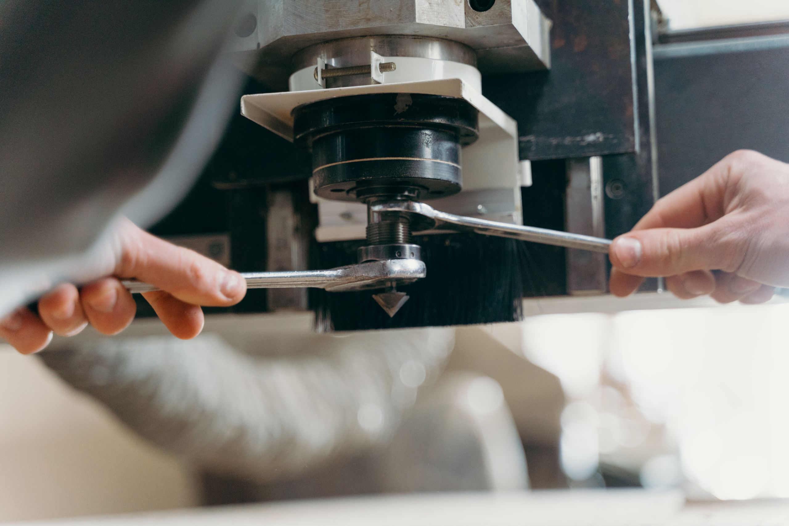
Insert runout causes one edge to carry more load and can leave feed marks or reduce tool life. Clean the cutter pockets, inspect screws and seats, torque inserts correctly, and verify axial runout. Wiper inserts can improve finish only when mounted and applied according to the cutter maker’s instructions.
Setup Checklist
- Clean the spindle taper, arbor, cutter body, pockets, inserts, and screws.
- Inspect the cutter body and every insert seat for damage.
- Torque inserts in the specified sequence and verify runout.
- Clamp and support the workpiece against axial and radial forces.
- Use supplier speed, feed per tooth, depth, width, and coolant guidance.
- Run a guarded test pass and inspect chips, sound, heat, finish, and insert wear.
Common Problems And Corrections
| Problem | Likely cause | Correction |
|---|---|---|
| Uneven finish | Runout, weak fixture, worn inserts | Restore alignment, support, and edge condition |
| Chatter | Long overhang, fine pitch, unstable engagement | Increase rigidity and adjust cutter or toolpath |
| Insert chipping | Impact, hard entry, wrong grade | Improve entry and select a tougher system |
| Excess spindle load | Too many teeth or heavy engagement | Reduce engagement or choose coarser pitch |
| Burrs | Exit direction, dull edge, weak support | Change path, insert, and edge support |
Selection Summary
The most useful face milling cutter advantages appear when diameter, lead angle, pitch, insert grade, edge geometry, runout, and toolpath match the machine and workpiece. Select for productivity without exceeding power, rigidity, fixture, or spindle limits. Browse the JeeFoo milling-tool range and follow applicable OSHA machine-guarding guidance.
Frequently Asked Questions
Why is a face mill productive?
Its large cutting path and multiple teeth can machine broad surfaces efficiently when power, rigidity, and chip flow are adequate.
Can one face mill both rough and finish?
Yes, if cutter geometry, inserts, stock allowance, runout, and cutting data support both operations; separate tools may be more consistent.
Why does one insert wear faster?
Common causes include pocket contamination, incorrect seating, axial runout, damaged screws, or uneven cutter-body geometry.

发表回复
要发表评论,您必须先登录。