
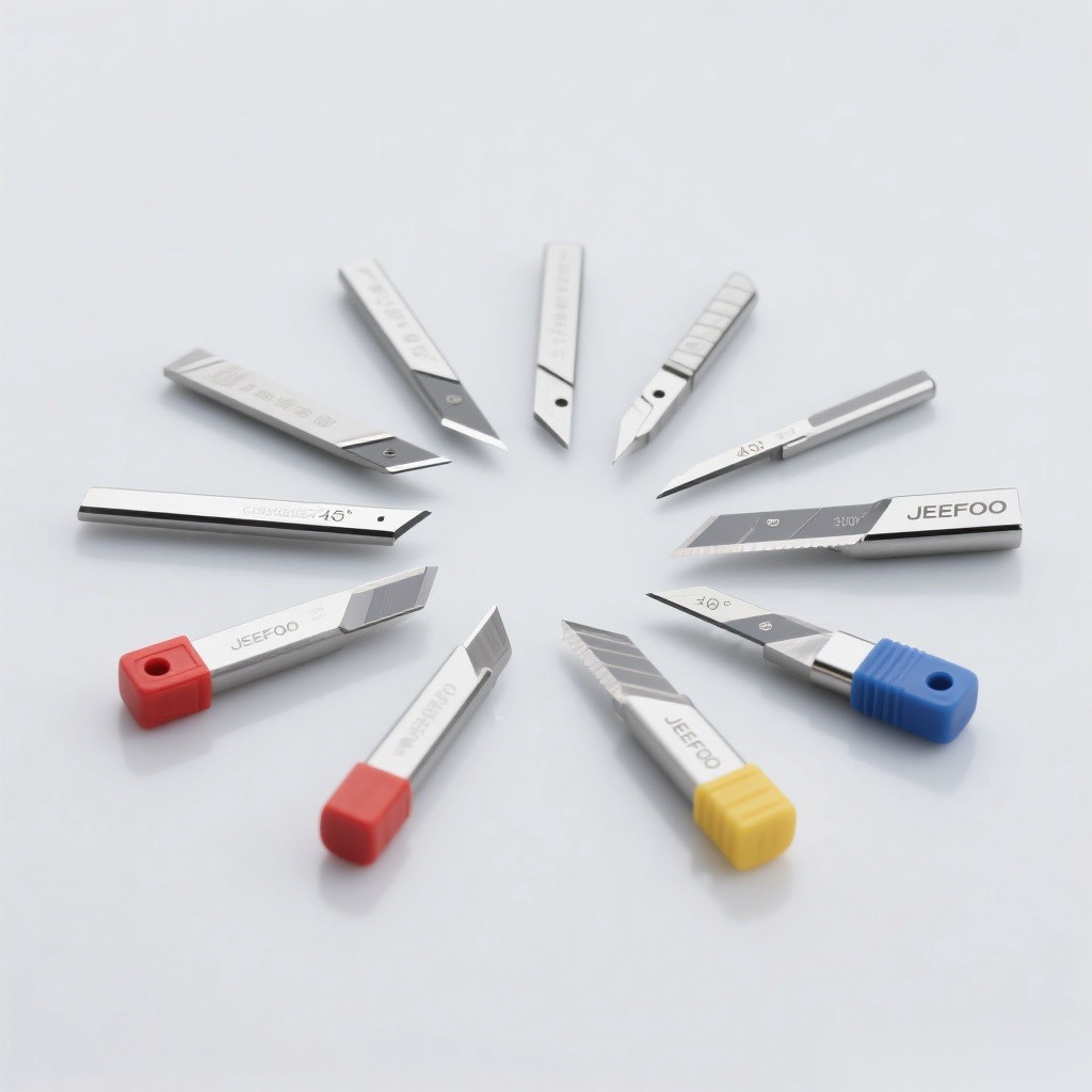
A carbide ball end mill is a rounded-tip milling cutter used for 3D engraving, contoured surfaces, curved grooves, finishing, and selected 2D cutting. It can machine acrylic and approved metals when the tool diameter, flute geometry, carbide grade, coating, reach, spindle data, feed, engagement, and cooling method match the material and machine.
What Is a Carbide Ball End Mill?
The cutting end is a hemisphere with a radius equal to half the cutter diameter. This shape follows three-dimensional surfaces without leaving the sharp corner produced by a flat end mill. Cutting speed approaches zero at the tool center, so tool tilt, path direction, stepover, chip evacuation, and finishing strategy strongly affect the result.
Main Applications
| Application | Why a ball end works | Key control |
|---|---|---|
| 3D engraving | Rounded tip follows sculpted geometry | Stepover and toolpath orientation |
| Freeform surface finishing | Produces continuous curved contact | Surface speed and scallop height |
| Round-bottom grooves | Tool radius creates a matching groove | Diameter, depth, and centerline position |
| Corner blending | Smoothly connects adjacent surfaces | Radius and finishing allowance |
| Selected 2D profiles | Can cut while leaving a radiused floor or edge | Verify that the rounded end matches the design |
Acrylic and Metal Applications
For acrylic, a polished edge and open flute can reduce heat and help evacuate chips before they melt or reweld. For black or ferrous metal, use only a carbide ball end mill grade and coating approved for the specific alloy and hardness. Metal cutting also requires suitable machine rigidity, workholding, coolant or air strategy, and guarded chip control.
Ball End Mill vs. Flat End Mill
| Feature | Ball end mill | Flat end mill |
|---|---|---|
| Tip shape | Rounded hemisphere | Flat cutting end |
| Best surface | Curves, 3D forms, radiused grooves | Floors, shoulders, square-bottom slots |
| Center cutting speed | Approaches zero | Varies by end geometry |
| Finishing pattern | Scallops controlled by stepover | Flat tracks and corner marks |
| Roughing efficiency | Usually lower for flat floors | Often higher for prismatic removal |
How to Select a Carbide Ball End Mill
- Define the smallest radius. The tool radius must fit the tightest concave feature.
- Choose diameter and reach. Use the largest rigid cutter that reaches every surface.
- Match flute count. Balance chip space, edge strength, and feed capability.
- Select carbide and coating. Match the acrylic or metal grade and cutting temperature.
- Minimize projection. Long reach increases deflection and chatter.
- Plan roughing and finishing. Leave uniform stock before the final 3D pass.
Stepover, Scallop Height, and Finish
A smaller stepover reduces scallop height and improves the visual finish but increases machining time. The correct value depends on ball radius, surface slope, tolerance, polishing allowance, machine accuracy, and required appearance. Use CAM simulation and the cutter maker’s data rather than applying one stepover to every surface.
Setup Checklist
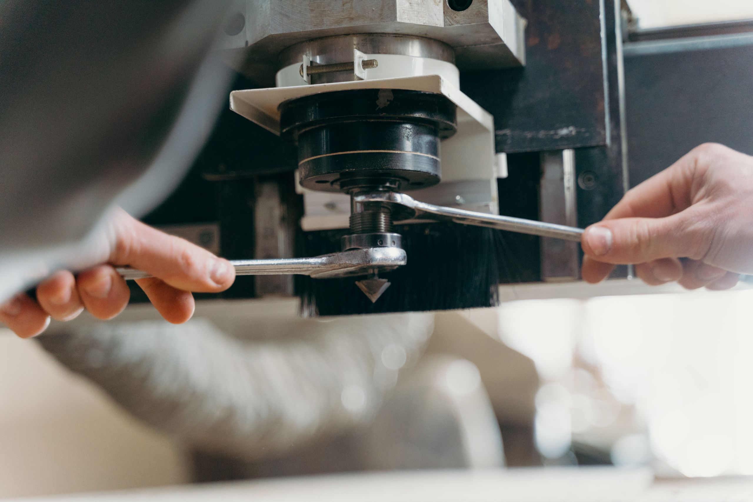
- Clean the holder and carbide shank; minimize tool projection.
- Measure runout near the rounded cutting edge.
- Clamp and support the workpiece against changing 3D cutting forces.
- Verify spindle rotation, entry, clearance, and collision-free toolpaths.
- Use manufacturer speed, feed, depth, width, and coolant data.
- Inspect chips, heat, surface marks, deflection, and edge wear after a test pass.
Common Problems and Corrections
| Problem | Likely cause | Correction |
|---|---|---|
| Visible scallops | Large stepover or wrong tool radius | Reduce stepover and verify geometry |
| Center rubbing | Cutting at the zero-speed tip region | Tilt the tool or change path orientation when allowed |
| Chatter | Long reach, weak setup, unstable engagement | Increase rigidity and adjust toolpath or data |
| Melted acrylic | Heat, rubbing, packed chips | Restore chip load and chip evacuation |
| Rapid metal wear | Wrong grade, coating, speed, or coolant | Match tool and process data to the alloy |
Selection Summary
Choose a carbide ball end mill for curved surfaces, 3D engraving, blending, and round-bottom features. Match the cutter to the smallest radius, material, reach, machine, and finish target, then control runout, stepover, engagement, and chip flow. Browse related tools in the JeeFoo cutter library and follow applicable OSHA machine-guarding guidance.
Frequently Asked Questions
What is a ball end mill used for?
It is used for 3D engraving, contoured surface finishing, corner blending, and round-bottom grooves.
Why can the tool center rub?
The effective cutting speed approaches zero at the center of the hemispherical tip, so orientation and path strategy matter.
Can one cutter machine acrylic and steel?
Only if the exact carbide grade, coating, flute geometry, and supplier data approve both materials; dedicated tools are often more reliable.

发表回复
要发表评论,您必须先登录。