
An aluminum substrate milling cutter is a specialized two-edge PCB router used to cut, slot, and profile aluminum-base boards, copper foil laminates, and IC carrier materials. Fishtail and drill-point designs support different entry methods. The tool should provide smooth chip evacuation, low heat, clean hole or slot walls, and minimal smearing in ductile metal layers.
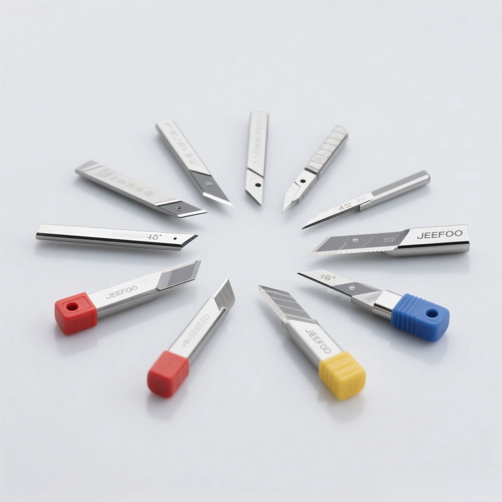
What Is an Aluminum Substrate Milling Cutter?
The cutter is designed for highly ductile metal-backed PCB materials that tend to smear, generate heat, and form built-up edge. A two-edge carbide geometry balances chip space, cutting stability, and wall finish. Tool diameter, tip style, cutting length, helix, coating, and edge preparation must match the board stack and router.
Fishtail vs. Drill-Point Design
| Design | Entry behavior | Best use | Caution |
|---|---|---|---|
| Fishtail | Flat-bottom cutting with corner points | Edge entry, slots, profiles, clean separation | Axial plunging depends on center geometry |
| Drill point | Pointed center supports axial entry | Piercing, internal slots, programmed entry | Point wear affects entry and hole wall |
| Two-edge router | Balanced cutting and chip space | General aluminum-base PCB routing | Feed must maintain chip thickness |
Suitable Materials and Applications
- Aluminum substrate and metal-core PCB panels.
- Full copper foil and highly ductile metal laminates.
- PBGA, BOC, and CSP packaging boards.
- IC carrier board slot forming and profiling.
- Mixed board stacks when the cutter is approved for every layer.
How to Select the Correct Cutter
- Define the entry. Use a drill-point style for validated axial entry or fishtail for edge entry and profiling.
- Match diameter and slot width. Account for runout, tool deflection, and finishing allowance.
- Choose cutting length. Use only enough length for the board stack to keep the tool rigid.
- Verify shank size. Match the collet exactly and check router runout.
- Match edge/coating. Use geometry specified for aluminum and copper smearing behavior.
- Confirm maker data. Maximum rpm, feed, depth, and stack height are tool-specific.
Chip Evacuation and Heat Control
Maintain enough chip load to cut rather than rub, while staying within tool strength. Vacuum extraction, directed air, or an approved mist system should remove ductile chips before recutting. Poor evacuation raises heat, stains walls, builds aluminum on the edge, and shortens tool life.
Setup Checklist
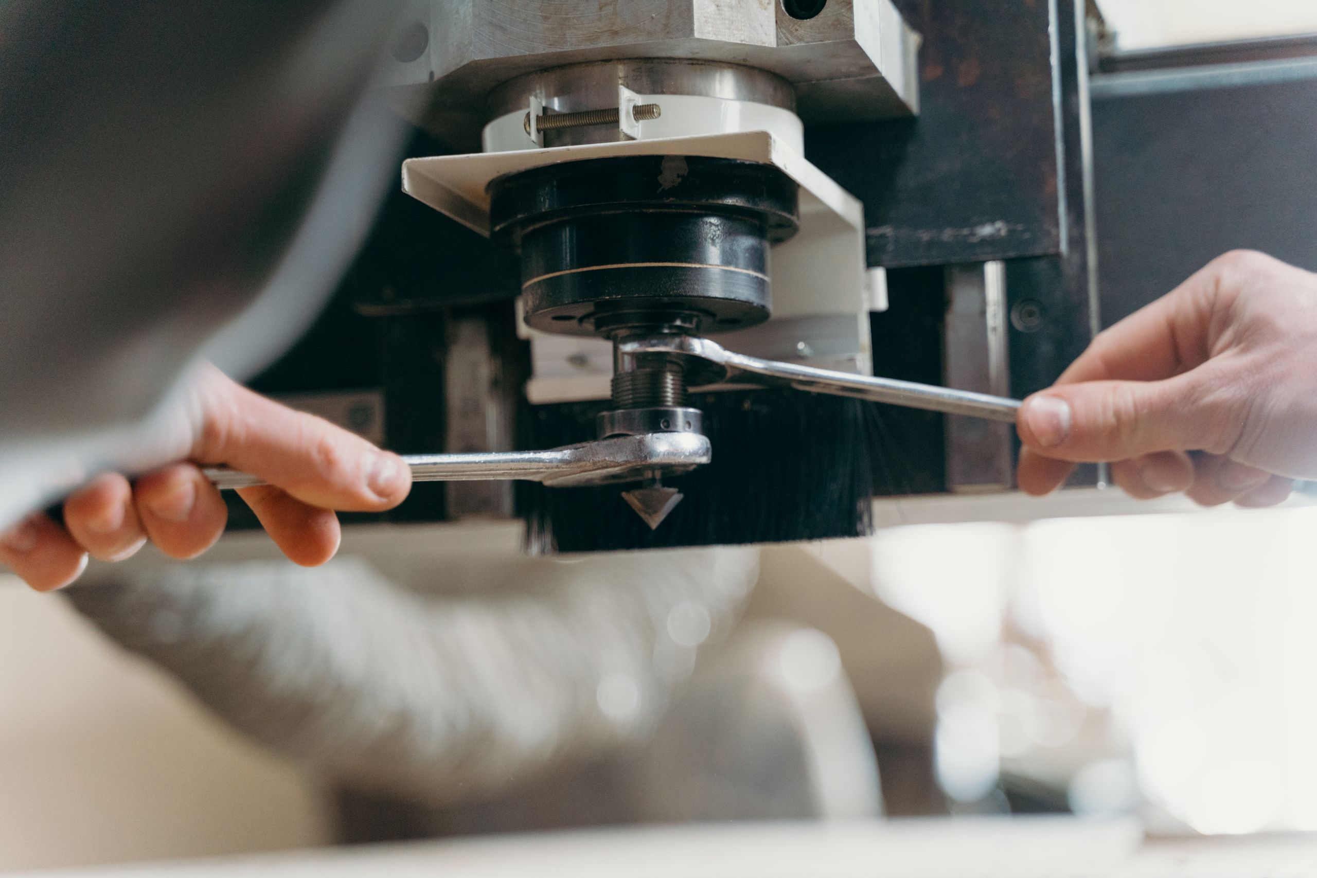
- Clean the collet and shank; minimize tool projection.
- Measure runout near the cutting edge.
- Support and clamp the panel flat without obstructing the path.
- Verify spindle rotation, entry strategy, and vacuum flow.
- Start with manufacturer rpm, feed, depth, and stack recommendations.
- Inspect wall finish, burrs, chips, and edge buildup after a test cut.
Common Problems and Fixes
| Problem | Likely cause | Correction |
|---|---|---|
| Wall smearing | Built-up edge, heat, dull cutter | Improve chip load, evacuation, and edge condition |
| Burrs | Worn edge, weak support, wrong feed | Replace tool and stabilize the board |
| Tool breakage | Runout, deep pass, chip packing, long overhang | Correct holding and reduce engagement |
| Oversize slot | Runout or deflection | Measure actual path and use finishing allowance |
| Discolored wall | Excess heat and recutting chips | Restore evacuation and cutting data |
Explore related PCB routing tools in the JeeFoo cutter library. Follow the router manufacturer’s instructions and relevant OSHA machine-guarding guidance.
Frequently Asked Questions
What is the cutter used for?
It profiles and slots aluminum-base PCB, copper foil laminates, and compatible IC carrier board materials.
When should a drill-point cutter be used?
Use it when the validated process requires axial entry or piercing before slotting; otherwise edge entry may reduce point load.
Why does aluminum stick to the cutter?
Rubbing, heat, poor chip removal, unsuitable geometry, or insufficient lubrication strategy can create built-up edge.
How can tool life be improved?
Control runout, overhang, chip load, depth, heat, board support, evacuation, and replacement timing using maker data.
For repeatable results, select an aluminum substrate milling cutter with verified carbide grade, two-edge geometry, cutting length, and entry style. An aluminum substrate milling cutter should create stable chips instead of rubbing, while the aluminum substrate milling cutter path remains supported and clear of recut debris.

发表回复
要发表评论,您必须先登录。