
Face milling cutter marks are usually caused by spindle runout, unequal insert height, vibration, incorrect feed or speed, poor workholding, or chip recutting. The pattern itself helps identify the fault: regular parallel lines often indicate feed marks, repeated waves suggest vibration, and one deep line per revolution often points to a high insert or runout.
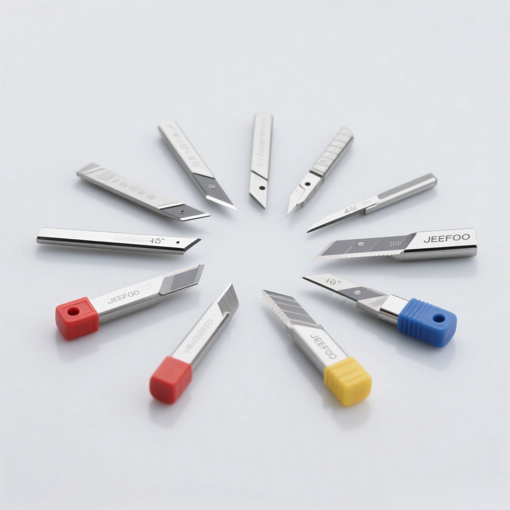
What Do Face Milling Cutter Marks Mean?
A milled face normally shows a consistent crosshatch or feed pattern. Marks become a problem when they are deep, uneven, wavy, widely spaced, or associated with poor flatness and roughness. Diagnose the pattern before changing cutting data because geometry, setup, and tool condition can produce similar symptoms.
Main Causes and Fast Corrections
| Observed pattern | Likely cause | First correction |
|---|---|---|
| One deep circular track | High insert, damaged pocket, or spindle runout | Clean pockets and measure insert height and runout |
| Even parallel feed lines | Feed per tooth too high or too few finishing teeth | Reduce feed or use a finishing/wiper insert |
| Wavy or repeating bands | Chatter from weak clamping, overhang, or resonance | Shorten overhang and stiffen the setup |
| Random scratches | Chip recutting or built-up edge | Improve air/coolant flow and chip evacuation |
| Step between passes | Head misalignment or workpiece movement | Check spindle tram, fixture support, and flatness |
1. Unequal Insert Height and Runout
If one insert projects farther than the others, it performs most of the cutting and leaves a repeated track. Remove every insert, clean the seats, inspect screws and pockets, torque correctly, and check axial runout with a suitable indicator. Replace damaged pockets or inserts rather than compensating with feed changes.
2. Vibration and Insufficient Rigidity
Chatter creates periodic waves and may damage insert corners. Common sources include excessive tool overhang, a weak arbor, loose gibs, poor workholding, a thin unsupported part, or cutting near a machine resonance. Shorten the assembly, improve support, reduce width of cut, and adjust speed away from the unstable range.
3. Incorrect Speed, Feed, and Engagement
- Feed too high: produces visible feed marks and may overload the leading insert.
- Feed too low: can cause rubbing instead of a stable chip, especially with a dull edge.
- Speed too low: may encourage built-up edge in ductile materials.
- Speed too high: increases heat and accelerates flank wear.
- Poor cutter position: creates unfavorable entry and exit conditions; adjust cutter offset where possible.
4. Insert Wear, Grade, and Geometry
Worn flanks, chipped corners, and built-up edge reproduce their shape on the workpiece. Use an insert grade and edge preparation suited to the material, machine power, and interrupted cutting. A wiper insert can improve finish, but only after runout and stability are controlled.
5. Chip Recutting and Coolant Delivery
Loose chips trapped under the cutter scratch the finished face. Direct air or coolant so chips leave the cutting zone, confirm that guards contain the stream, and avoid coolant conditions that cause repeated thermal shock when the insert grade is intended for dry cutting.
Face Milling Troubleshooting Sequence
- Clean the cutter, pockets, holder taper, and spindle interface.
- Inspect inserts for wear, chipping, and built-up edge.
- Measure axial and radial runout; verify equal insert seating.
- Check fixture rigidity, workpiece support, and tool overhang.
- Confirm cutter diameter, pitch, grade, and geometry suit the material.
- Restore the manufacturer’s starting speed and feed, then change one variable at a time.
- Make a short test pass and compare the new pattern and measured roughness.
For related selection guidance, see the JeeFoo cutting-tool resources. Always follow the machine manual and applicable OSHA machine-guarding requirements during inspection and testing.
Frequently Asked Questions
Are face milling cutter marks always a defect?
No. A uniform feed pattern can be normal. It becomes unacceptable when it exceeds the specified roughness, flatness, appearance, or sealing requirement.
Why does one insert leave a deeper line?
The insert may sit high because of dirt, pocket damage, incorrect torque, thickness variation, or holder runout. Inspect and measure rather than simply reducing feed.
Can a wiper insert remove milling marks?
A wiper can reduce feed marks and improve finish, but it cannot correct excessive runout, chatter, loose workholding, or a damaged cutter body.
What should be checked first?
Start with cleanliness, insert condition, seating, and runout. These checks are quick and commonly reveal the source of a repeated surface pattern.

发表回复
要发表评论,您必须先登录。