
Milling insert classification is based on six main factors: insert shape, clearance angle, tolerance class, clamping or chipbreaker design, size and cutting-tool material or coating. These features determine edge strength, accessibility, accuracy, chip flow and suitability for steel, stainless steel, cast iron, non-ferrous metal or hardened material.
How Are Milling Inserts Classified?
Indexable inserts are identified by standardised letters and numbers that describe their geometry and dimensions. A complete insert designation should be interpreted together with the manufacturer’s grade and chipbreaker code. The holder pocket must match the insert shape, clearance, size, thickness and mounting method exactly.
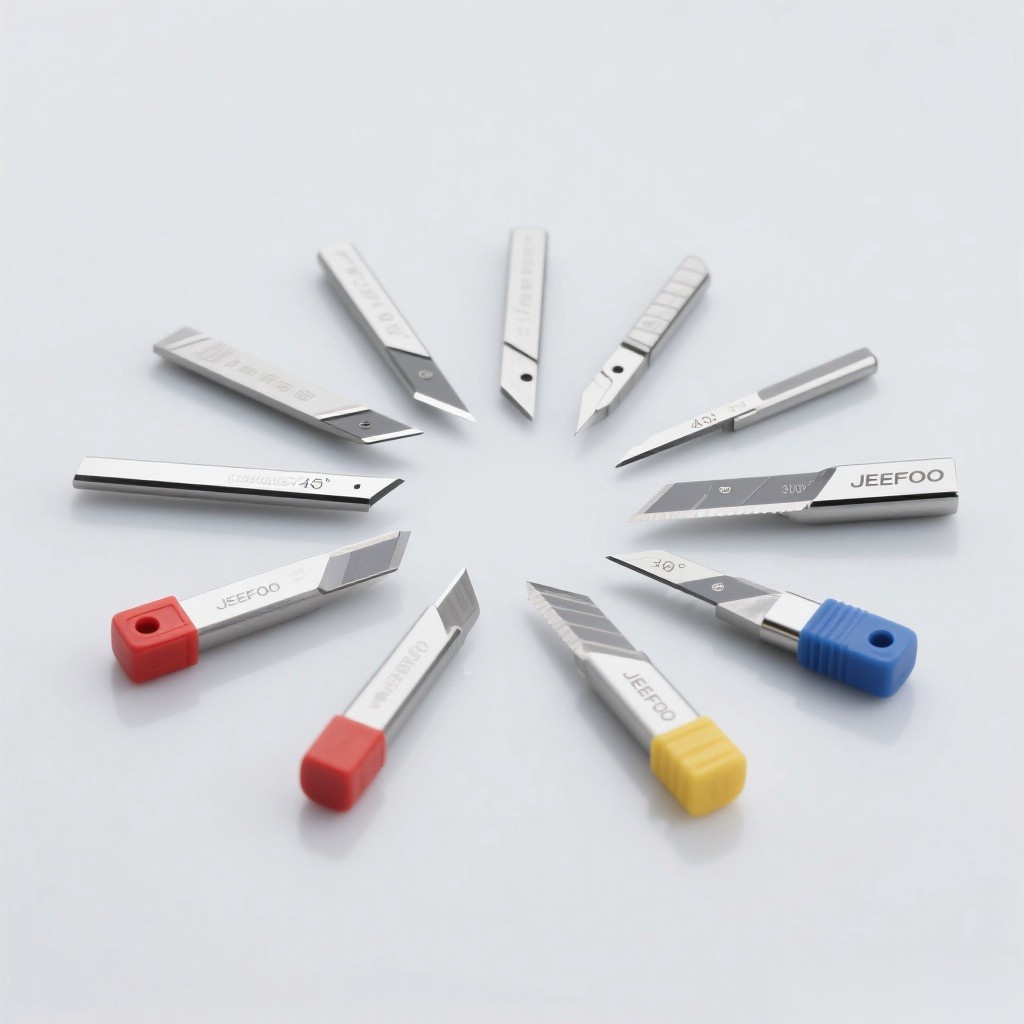
Classification at a Glance
| Factor | What it describes | Why it matters |
|---|---|---|
| Shape | Square, round, triangular, rhombic and other forms | Edge strength, approach angle and accessibility |
| Clearance angle | Relief below the cutting edge | Positive or negative cutting geometry |
| Tolerance class | Dimensional and indexing accuracy | Runout, repeatability and finish |
| Chipbreaker / clamping | Top geometry, hole and fixing method | Chip flow, edge security and cutting force |
| Size | Inscribed circle, thickness and corner radius | Holder fit, depth capability and edge strength |
| Grade and coating | Carbide substrate, ceramic, CBN, PCD or coating | Material compatibility, speed and tool life |
1. Insert Shape
Square inserts provide strong corners and multiple indexable edges for general face and shoulder milling. Round inserts offer very strong edges and smooth entry for profiling or heavy roughing. Triangular and rhombic shapes provide different approach angles and access to shoulders or complex features. Shape must match the cutter body pocket.
2. Clearance Angle
A positive-clearance insert has relief built into its side walls and normally reduces cutting force. A zero-clearance or negative-style insert relies on holder geometry and can provide strong, double-sided edges. Positive geometry is often useful on lower-power machines, non-ferrous materials and thin parts; negative geometry suits rigid setups and stronger edges.
3. Tolerance Class
Tolerance class controls insert dimensions and the repeatability of indexed edges. Tighter classes help minimise runout and support consistent finish, but cutter-body accuracy, pocket condition, screw torque and spindle runout are equally important. A precision insert cannot compensate for a damaged seat.
4. Chipbreaker and Clamping Design
Chipbreaker geometry controls chip curl, cutting force and edge support. Light, medium and heavy machining designs use different rake surfaces and edge preparations. Inserts may use a centre hole, countersink, clamp or screw system. The clamping style must correspond to the cutter body and specified hardware.
5. Insert Size and Corner Radius
Inscribed circle, thickness and length define the physical size. Corner radius affects edge strength and surface finish: a larger radius supports heavier cuts but increases radial force, while a smaller radius reduces load and reaches smaller features. Feed and depth should remain compatible with the radius.
6. Tool Material, Grade and Coating
| Tool material | Typical strength | Common application area |
|---|---|---|
| Coated carbide | Balanced wear resistance and toughness | Steel, stainless steel and cast iron grades |
| Uncoated carbide | Sharp edge and good thermal conductivity | Aluminium and non-ferrous materials |
| Ceramic | High hot hardness | Selected cast iron and hardened-material operations |
| CBN | High wear resistance on hard ferrous materials | Hardened steel and finishing |
| PCD | Extreme abrasion resistance | Aluminium, composites and non-ferrous materials |
Workpiece Material Groups
Manufacturers commonly group workpieces into steel, stainless steel, cast iron, non-ferrous metal, heat-resistant alloy and hardened material families. Grade colours and exact codes vary by supplier. Always use the cutter maker’s chart rather than assuming that similarly coloured inserts from different brands are equivalent.
How to Select a Milling Insert
- Identify the cutter body and its exact compatible insert designation.
- Classify the workpiece material and hardness.
- Define roughing, medium machining or finishing.
- Select geometry for cutting force, chip control and edge strength.
- Choose grade and coating for speed, coolant and interruption level.
- Confirm corner radius, tolerance and wiper requirements.
Safety and Installation
Clean the pocket, inspect the seat and use only the specified screw or clamp. Tighten to the recommended torque and replace damaged hardware. Never mix incompatible inserts with a cutter body. Follow manufacturer instructions and applicable OSHA machine-guarding guidance.
Frequently Asked Questions
What does a milling insert code describe?
It describes standard features such as shape, clearance, tolerance, clamping style and size; supplier codes then specify chipbreaker and grade.
Can inserts from different brands be interchanged?
Only when every relevant standard dimension and clamping feature matches the cutter body. Grade and chipbreaker performance may still differ.
Which insert is best for aluminium?
A sharp positive-geometry, polished carbide or PCD insert is common, but the alloy, silicon content, operation and cutter body determine the final choice.
Browse our precision cutting tool solutions or contact JEEFOO with your cutter body, workpiece material, operation and insert designation.


发表回复
要发表评论,您必须先登录。