
A taper shank end mill combines a fluted cutting body with an integral tapered shank that seats directly in a compatible machine spindle or adapter. This Taper Shank End Mill Guide explains eight milling features that affect rigidity, torque transmission, accuracy, tool change, chip evacuation, reach, finish, and safe application.
What is a taper shank end mill?
Table of Contents
A taper shank end mill is a milling cutter whose shank uses a specified machine taper rather than a straight cylindrical shank. The taper provides concentric location and a large contact area. Depending on the standard, retention may use a tang, drawbar thread, pull stud, or another dedicated mechanism. The exact taper and retention system must match the machine.
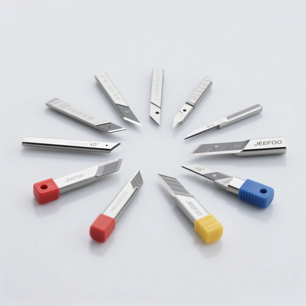
Taper Shank End Mill Guide: feature summary
| Feature | Practical benefit | What to verify |
|---|---|---|
| Integral taper | Rigid, concentric location | Taper standard and size |
| Large contact area | Stable torque transfer | Clean, undamaged mating surfaces |
| Reduced holder stack | Potentially shorter projection | Actual gauge length and clearance |
| Flute geometry | Controls cutting and chip flow | Material, operation, flute count |
| End geometry | Defines plunging and corner form | Center cutting, radius, ball or square end |
| Retention system | Prevents axial movement | Drawbar, tang, pull stud, or thread |
1. Direct taper-to-spindle location
The Taper Shank End Mill Guide begins with interface identification. Morse, Brown & Sharpe, R8, steep-taper, and other systems are not interchangeable merely because they look similar. Correct seating requires the exact standard, size, angle, gauge line, and retention method specified by the machine builder.
2. Rigidity and overhang control
An integral taper can reduce the number of interfaces between spindle and cutting edge. Fewer joints and a short projection can improve stiffness, reduce chatter, and support dimensional consistency. However, total gauge length still matters. Use the shortest cutter that clears the workpiece and fixture, and avoid unnecessary flute length.
3. Torque transmission and retention
The taper contact transmits part of the cutting load, while a tang, key, drawbar, pull stud, or drive feature may provide retention or additional torque capacity. Never rely on friction alone when the machine design requires positive retention. Confirm that threads, tangs, and drive features are intact and fully compatible.
4. Cutting-end geometry
- Square end: produces flat floors and near-square shoulders.
- Corner radius: strengthens the edge and leaves a defined fillet.
- Ball nose: supports contoured and 3D surfaces.
- Center-cutting end: can enter axially within the maker’s limits.
- Non-center-cutting end: requires a predrilled entry, ramp, or side approach.
The Taper Shank End Mill Guide recommends choosing the end form from the feature first, then confirming diameter, flute length, neck clearance, and allowable radial or axial engagement.
5. Flute count and chip evacuation
Fewer flutes provide larger chip valleys for slotting, aluminum, and high-engagement cutting. More flutes can raise productivity and improve finish in steel when chip space remains sufficient. Recalculate feed from chip load, flute count, and spindle speed. A feed that is too low can cause rubbing, heat, and rapid wear.
6. Helix, rake, substrate, and coating
Helix and rake influence cutting force, chip lifting, edge strength, and finish. High-speed steel offers toughness and is often economical at lower speeds. Carbide provides stiffness and wear resistance for higher productivity in a rigid setup. Coating and edge preparation must suit steel, stainless, cast iron, aluminum, or another workpiece material.
| Workpiece | Useful starting traits | Main risk |
|---|---|---|
| Aluminum | Sharp polished flutes, large chip space | Built-up edge |
| Steel | Carbide or HSS with suitable coating | Heat and flank wear |
| Stainless steel | Positive geometry, tough grade | Work hardening |
| Cast iron | Abrasion-resistant edge | Abrasive dust and wear |
7. Runout and taper condition
Dirt, burrs, fretting, corrosion, or dents on either taper can prevent full contact and increase runout. Clean both surfaces with approved methods, inspect the gauge line, and measure runout near the cutting edge. Do not stone, grind, or modify a precision taper unless an authorized repair procedure explicitly permits it.
8. Tool changes and machine compatibility
Integral taper tools may simplify a dedicated setup, but inventory and changeover depend on the machine. Confirm spindle orientation, retention force, pull-stud specification, drawbar condition, tool-change envelope, and balance or RPM limits. The Taper Shank End Mill Guide treats the machine manual as the controlling source.
Selection checklist
- Identify the exact taper standard, size, and retention method.
- Match cutter diameter and end geometry to the feature.
- Use the shortest reach and flute length that provide clearance.
- Select flute count, substrate, coating, and helix for the material.
- Verify machine RPM, torque, power, and tool-change limits.
- Inspect taper contact, runout, and cutting edges before use.
- Start with manufacturer cutting data and adjust for engagement and rigidity.
Safe setup and operation
Stop and isolate the machine before installing or removing tooling. Keep mating tapers clean, use the specified retention components, verify clearance, and keep guarding in place. Review the machine builder’s procedure and authoritative OSHA machine-guarding guidance. This does not replace site training or a task-specific risk assessment.
Common mistakes
- Assuming visually similar taper systems are interchangeable.
- Ignoring required positive retention.
- Using excess projection or flute length.
- Installing a taper with chips, burrs, or fretting damage.
- Selecting flute count without checking chip evacuation.
- Running generic cutting data without accounting for engagement and rigidity.
For related cutting-tool resources and product support, visit Guangzhou JeeFoo Tools.
Frequently asked questions
Is a taper shank end mill more rigid than a straight-shank tool?
It can reduce interfaces and projection in a compatible setup, but actual rigidity depends on gauge length, taper condition, spindle design, cutter diameter, and cutting forces.
Can different machine tapers be interchanged?
No. Use only the exact taper, size, retention component, and machine specification. A similar appearance does not establish compatibility.
Why does a taper shank cutter chatter?
Likely causes include excess reach, poor taper contact, runout, weak workholding, worn edges, unsuitable speed or engagement, and insufficient machine rigidity.
How should the taper be maintained?
Keep it clean, dry, and protected from impacts; inspect for burrs, corrosion, and fretting; follow the machine and tool maker’s approved maintenance procedure.
Bottom line: use this Taper Shank End Mill Guide to verify the interface first, then optimize cutter geometry, flute design, material, coating, reach, runout, cutting data, and safety.


发表回复
要发表评论,您必须先登录。