
A “tungsten steel” milling cutter usually means a cemented tungsten-carbide cutter: hard tungsten-carbide particles bonded in a metallic matrix, commonly cobalt, and formed into a rigid wear-resistant cutting tool. This Tungsten Carbide Milling Cutter Guide explains composition, advantages, limits, geometry, coatings, feed and speed, inspection, and safe CNC use.
Is tungsten steel the same as carbide?
The Tungsten Carbide Milling Cutter Guide clarifies that in cutting-tool trade language, “tungsten steel” often refers to cemented carbide rather than conventional steel. The tool is a composite: tungsten-carbide grains provide hardness and abrasion resistance, while the binder adds toughness. Grade, grain size, binder percentage, edge preparation, and coating determine performance; not all carbide tools are equivalent.
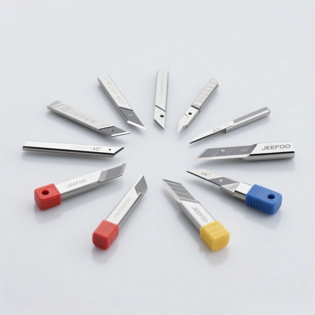
Tungsten Carbide Milling Cutter Guide: 10 rules
- Match the grade to the material: carbide hardness and toughness must suit the alloy, hardness, and interruption.
- Control runout: carbide is rigid but sensitive to unequal edge loading, especially at small diameters.
- Minimize overhang: short projection reduces deflection, chatter, and breakage.
- Choose flute count by chip volume: fewer flutes clear large chips; more flutes add edges and core strength.
- Select geometry, not only coating: rake, helix, edge radius, and flute polish strongly affect cutting.
- Use coating by application: the best coating depends on heat, adhesion, abrasiveness, and work material.
- Maintain real chip load: very low feed can rub and wear the edge instead of cutting.
- Control engagement: constant-load paths protect carbide from shock and excessive bending.
- Inspect before failure: track wear, size, finish, and load rather than waiting for a broken tool.
- Use the correct holder: clean, rigid, low-runout clamping is essential to carbide performance.
Advantages and limitations
| Characteristic | Advantage | Limitation |
|---|---|---|
| High hardness | Resists abrasive wear | Can chip under shock |
| High stiffness | Controls deflection and size | Less forgiving of runout and vibration |
| Hot hardness | Supports higher cutting speed | Excess heat still damages coating and edge |
| Fine edge geometry | Accurate machining and finish | Edge preparation must match the material |
| Coating compatibility | Extends life in many alloys | Wrong coating can increase adhesion or wear |
Choose the cutter shape
- Square end mill: slots, pockets, shoulders, and profiles.
- Ball nose end mill: 3D contours, molds, and dies.
- Corner-radius end mill: stronger tip for roughing and durable profiling.
- Roughing end mill: serrated geometry divides chips during heavy removal.
- Chamfer mill: beveling, countersinking, and deburring.
- Thread mill: interpolated internal or external threads.
- Long-neck or reduced-shank tool: deep access with controlled engagement.
Choose flute count
The Tungsten Carbide Milling Cutter Guide uses chip evacuation as the first flute-count test. One or two flutes provide large chip spaces for plastics, wood, and full-slot work. Three flutes balance evacuation and core strength in aluminum. Four or more flutes offer additional edges and a stronger core for steel, finishing, and low radial engagement. These are starting patterns, not absolute rules.
Select a coating
| Tool surface | Common reason | Important caution |
|---|---|---|
| Uncoated polished carbide | Sharp edge and low adhesion in many aluminum or plastic jobs | Lower heat and abrasive protection |
| TiAlN/AlTiN family | Heat and wear resistance in many steels | Not automatically best for aluminum |
| DLC or low-friction coating | Reduced adhesion in selected nonferrous work | Confirm temperature and material compatibility |
| Diamond coating | Abrasion resistance in graphite and composites | Not suitable for ferrous cutting due to chemical interaction |
Diameter, reach, and rigidity
Choose the largest cutter that fits the feature, then minimize flute length, neck length, and holder projection. Long-reach carbide tools need lower engagement because stiffness drops rapidly with length. Check holder and neck clearance across the entire path; a short cutting edge cannot safely cut deeper simply because the shank is long.
Feed, speed, and chip load
Start from the manufacturer data for the exact cutter and work material. Program feed from spindle speed × flute count × chip load per tooth. Adjust for radial engagement, axial depth, overhang, machine power, coolant, and toolpath. Excessively low chip load causes rubbing; excessive load causes deflection, chipping, or breakage.
Setup checklist
- Confirm diameter, flute length, reach, corner geometry, coating, and maximum RPM.
- Clean the spindle interface, holder, collet, and shank.
- Measure runout for small tools, finishing, and long-life work.
- Use the shortest practical holder projection.
- Clamp the workpiece against all cutting-force directions.
- Verify entry method and center-cutting capability.
- Provide coolant, air, extraction, or dust control suited to the material.
- Run a controlled test and inspect chips, sound, load, size, and finish.
Troubleshooting
| Problem | Likely cause | Corrective check |
|---|---|---|
| Edge chipping | Runout, shock, weak edge preparation | Measure setup and match geometry |
| Tool breakage | Collision, chip packing, excessive load | Review path, flute space, engagement |
| Rapid flank wear | High speed, abrasion, wrong coating | Verify grade, coating, surface speed |
| Built-up edge | Adhesive material, rubbing, poor lubrication | Use sharp geometry and correct chip load |
| Chatter | Long overhang or low rigidity | Shorten setup and adjust engagement |
| Poor finish | Wear, runout, deflection, wrong feed | Inspect edge, holder, path, parameters |
Inspection and tool-life management
Inspect edges under magnification and track machining time, cutting distance, spindle load, dimensions, and surface quality. Define a wear or size limit before catastrophic failure. Replace or recondition through an approved service when the edge no longer meets the process requirement.
Safety requirements
Use suitable guarding, workholding, chip control, and personal protection. Follow OSHA machine-guarding guidance and the machine builder’s instructions. Never touch, measure, or clear chips near a rotating tool. For related products, visit JeeFoo precision carbide tools.
Frequently asked questions
Is tungsten carbide harder than steel?
Yes, cemented carbide is much harder and more wear resistant than common tool steels, but it is also less tolerant of shock and bending.
Can carbide mill hardened steel?
Suitable carbide grades and coatings can machine some hardened steels, but hardness, geometry, machine rigidity, toolpath, and supplier limits must be verified.
Why do small carbide tools break?
Common causes are runout, excess overhang, chip packing, collision, abrupt engagement, improper chip load, or continuing after edge damage.
Apply this Tungsten Carbide Milling Cutter Guide from material and feature to grade, geometry, coating, holder, parameters, inspection, and replacement limit.


发表回复
要发表评论,您必须先登录。