
A three-side milling cutter has cutting edges on its outside diameter and on both side faces, allowing it to machine a slot bottom and both walls in one pass. Also called a side-and-face milling cutter, it is used for fixed-width grooves, steps, shoulders, side faces, and straddle-milling operations. This Three Side Milling Cutter Guide explains selection, arbor setup, width control, feeds, inspection, and safety.
How does a three-side milling cutter work?
The Three Side Milling Cutter Guide starts with peripheral teeth removing material from the slot bottom while auxiliary cutting edges on both sides generate the walls. Side clearance prevents the cutter body from rubbing against the new surfaces. Because three cutting zones can engage together, the tool can produce an accurate groove efficiently but also creates substantial radial and axial forces.
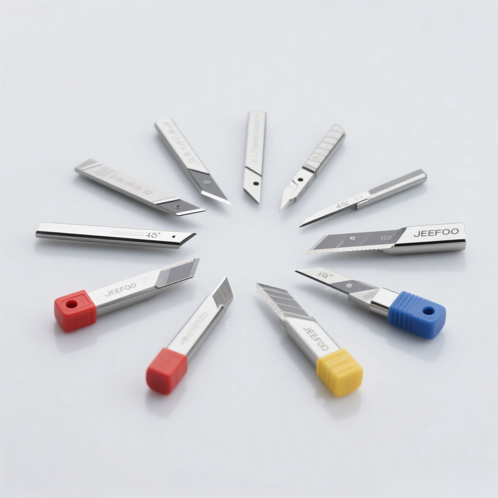
Three Side Milling Cutter Guide: 9 essential rules
- Match cutter width to the groove: include tolerance, runout, wear, and any finishing allowance.
- Choose diameter for access and rigidity: the body must clear the feature while fitting the machine and arbor.
- Use coarse pitch for heavier cuts: larger chip spaces reduce packing in deep slots.
- Use fine pitch for lighter finishing: more edges can improve stability when chip volume remains controlled.
- Support the arbor: place the cutter near the spindle and use proper outboard support where designed.
- Control side forces: fixture the workpiece against both feed and axial cutting loads.
- Plan chip evacuation: chips trapped between both walls can scratch the slot and overload teeth.
- Measure width and runout: one high side edge can make the groove oversize or tapered.
- Use a test cut: verify actual slot width, wall finish, bottom finish, and burr direction.
Main applications
- Fixed-width slots and keyway-type grooves
- Steps and shoulders requiring side and bottom cutting
- Side-face milling on components and plates
- Straddle milling with two cutters spaced on one arbor
- Grooves in medium-strength steels and approved nonferrous materials
- Superhard or specialty versions for compatible difficult-to-cut materials
- Production work where a form must remain consistent across many parts
Solid, staggered-tooth, and indexable types
| Type | Main strength | Typical selection reason |
|---|---|---|
| Solid HSS cutter | Tough, resharpenable edges | General work and smaller sizes |
| Solid carbide cutter | Rigidity and wear resistance | Higher speed and accurate small features |
| Staggered-tooth cutter | Improved chip flow and distributed load | Deeper slots and heavier cutting |
| Indexable side-and-face mill | Replaceable cutting edges | Larger diameters and production machining |
| Superhard-edge cutter | Application-specific wear resistance | Compatible abrasive or difficult materials |
Choose width, diameter, and tooth pitch
The Three Side Milling Cutter Guide begins with the finished groove drawing. Cutter width should match the required feature or leave a controlled finishing allowance. A larger diameter improves access to deeper walls but increases torque and collision envelope. Tooth pitch must leave enough room for the expected chip volume; too many teeth in a deep slot can pack chips and generate heat.
Arbor mounting and support
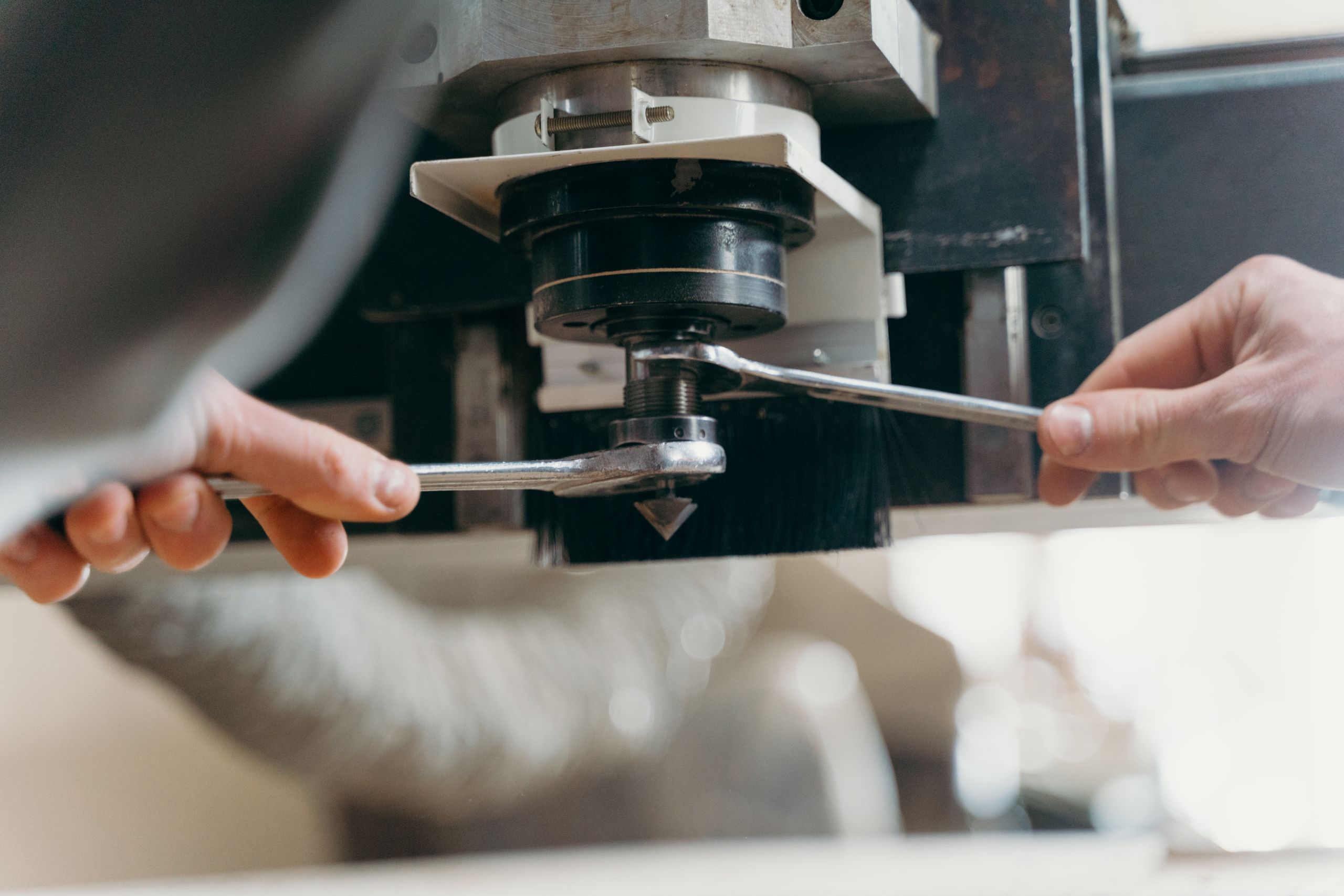
- Clean the spindle taper, arbor, cutter bore, key, spacers, nut, and support bearing.
- Confirm cutter rotation and tooth direction before mounting.
- Position the cutter as close to the spindle as the workpiece permits.
- Use precision spacers and the correct key without improvised components.
- Engage the arbor support according to the machine builder’s procedure.
- Tighten the arbor nut correctly and verify cutter seating.
- Measure radial runout and both side faces before production.
Conventional and climb milling
Climb milling can improve finish and edge life on a rigid machine with controlled backlash, but it pulls the workpiece into the cut. Conventional milling pushes against the feed and may be safer on older machines with backlash. The fixture must resist the chosen force direction, and the machine builder’s instructions take priority.
Feed, speed, and depth
Calculate surface speed from cutter diameter and spindle speed. Program feed from spindle speed, active teeth, and recommended chip load per tooth. Adjust for full-slot engagement, side-edge contact, arbor length, cutter width, machine power, work material, and coolant. Deep grooves may require staged passes rather than one full-depth cut.
Control slot width and finish
- Measure actual cutter width after sharpening or reconditioning.
- Check side-face runout and axial seating on the arbor.
- Use consistent stock allowance before a finishing pass.
- Prevent chips from recutting between the groove walls.
- Keep the arbor rigid and supported near the cutter.
- Inspect wall taper, bottom flatness, burr location, and surface pattern.
- Use compensation only after measuring the real cut.
Straddle milling
The Three Side Milling Cutter Guide also covers straddle milling, where two side-and-face cutters are spaced on an arbor to machine parallel faces in one operation. Precision spacers set the distance between cutters. Both tools must be compatible in diameter, cutting direction, tooth phase, and load. Verify arbor capacity and fixture resistance because simultaneous contact can create high cutting forces.
Troubleshooting
| Problem | Likely cause | Corrective check |
|---|---|---|
| Groove oversize | Side runout, wear, wrong cutter width | Measure tool, seating, arbor, and cut |
| Tapered walls | Deflection or unequal side edges | Improve support, inspect faces, reduce load |
| Chatter | Long arbor or heavy engagement | Shorten setup, improve support, stage depth |
| Rough bottom | Peripheral tooth wear or high tooth | Inspect circumference and radial runout |
| Scratched walls | Chip recutting or body rubbing | Improve evacuation and check clearance |
| Broken teeth | Chip packing, shock, foreign material | Use correct pitch, entry, and material control |
Inspection and maintenance
Inspect peripheral teeth, both side edges, cutter body, bore, keyway, arbor, spacers, nut, and support bearing. Clean chips and corrosion without damaging precision surfaces. Record cutter width and diameter after regrinding because both may affect program data and the finished groove.
Safety checklist
- Use guards suitable for the cutter diameter and exposed side edges.
- Never exceed cutter, arbor, or machine speed limits.
- Do not run a cracked, chipped, loose, or incorrectly keyed cutter.
- Isolate the machine before measuring or clearing chips.
- Clamp the workpiece against radial, axial, and feed forces.
- Stand clear during the initial test run.
Follow OSHA machine-guarding guidance and the machine builder’s procedures. For related products, visit JeeFoo precision milling tools.
Frequently asked questions
Why is it called a three-side cutter?
It cuts on three zones: the outside diameter plus the two side faces. This allows the bottom and both walls of a groove to be generated together.
Can it cut a slot in one pass?
It can when the tool, machine, material, depth, power, chip evacuation, and fixture support the load. Deep or demanding slots may require staged passes.
What controls the final slot width?
Cutter width, side-edge runout, wear, deflection, arbor seating, machine alignment, and any path compensation together determine the measured result.
Apply this Three Side Milling Cutter Guide from drawing to cutter, arbor, support, parameters, inspection, and maintenance.

发表回复
要发表评论,您必须先登录。