
A correct PCD combination milling cutter setup aligns a multi-profile diamond tool with the spindle, holder, workpiece datum, machine limits, and toolpath before production begins. This PCD Combination Milling Cutter Setup guide covers 11 best practices for runout, balance, profile offsets, feeds, chip control, test cutting, inspection, and reconditioning.
Why setup matters for a combination cutter
Table of Contents
A combination cutter may machine several diameters, steps, bevels, radii, grooves, or edge profiles in one pass. If the tool is misaligned, a small error can affect multiple part features at once. Polycrystalline diamond offers long wear life in abrasive panels and composites, but the edge is vulnerable to shock, vibration, and improper mounting.
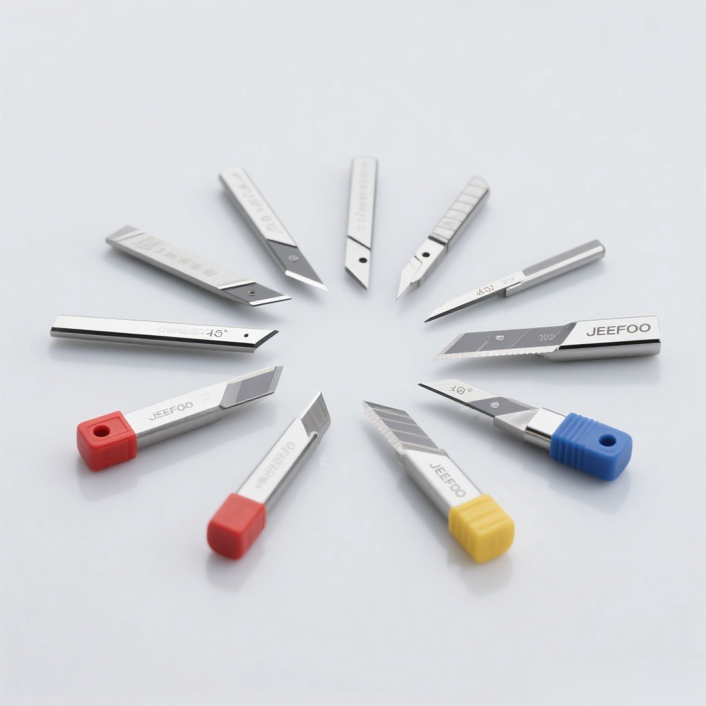
PCD Combination Milling Cutter Setup: 11 best practices
- Verify tool identity: match model, profile drawing, rotation, bore or shank, edge layout, and maximum RPM.
- Inspect before mounting: look for chipped diamond, cracks, loose segments, corrosion, and body damage.
- Clean every interface: remove dust and resin from the spindle, holder, bore, shank, spacers, and clamping faces.
- Mount to specification: use approved components and manufacturer torque values.
- Measure runout: check at the specified body or cutting reference, not an arbitrary surface.
- Confirm balance and speed: never exceed the marked RPM or machine limitation.
- Set profile offsets: establish the correct axial and radial datum for every combined feature.
- Check collision clearance: simulate the largest body diameter, holder, neck, and clamps through the whole path.
- Control engagement: avoid shocking all profile sections into the work at once unless approved.
- Run a representative test: use the real material stack and measure every critical feature.
- Document the result: record tool ID, offsets, feed, speed, finish, load, and service history.
Pre-installation inspection
| Inspection point | Acceptable condition | Reject or investigate |
|---|---|---|
| Diamond edge | Continuous sharp edge | Chips, cracks, flats, missing segment |
| Tool body | Clean and undamaged | Cracks, dents, corrosion, heat marks |
| Mounting surface | Clean and burr-free | Debris, fretting, raised damage |
| Fasteners or segments | Secure and complete | Loose or altered components |
| Markings | Readable model and RPM | Unknown identity or speed limit |
Mounting and runout control
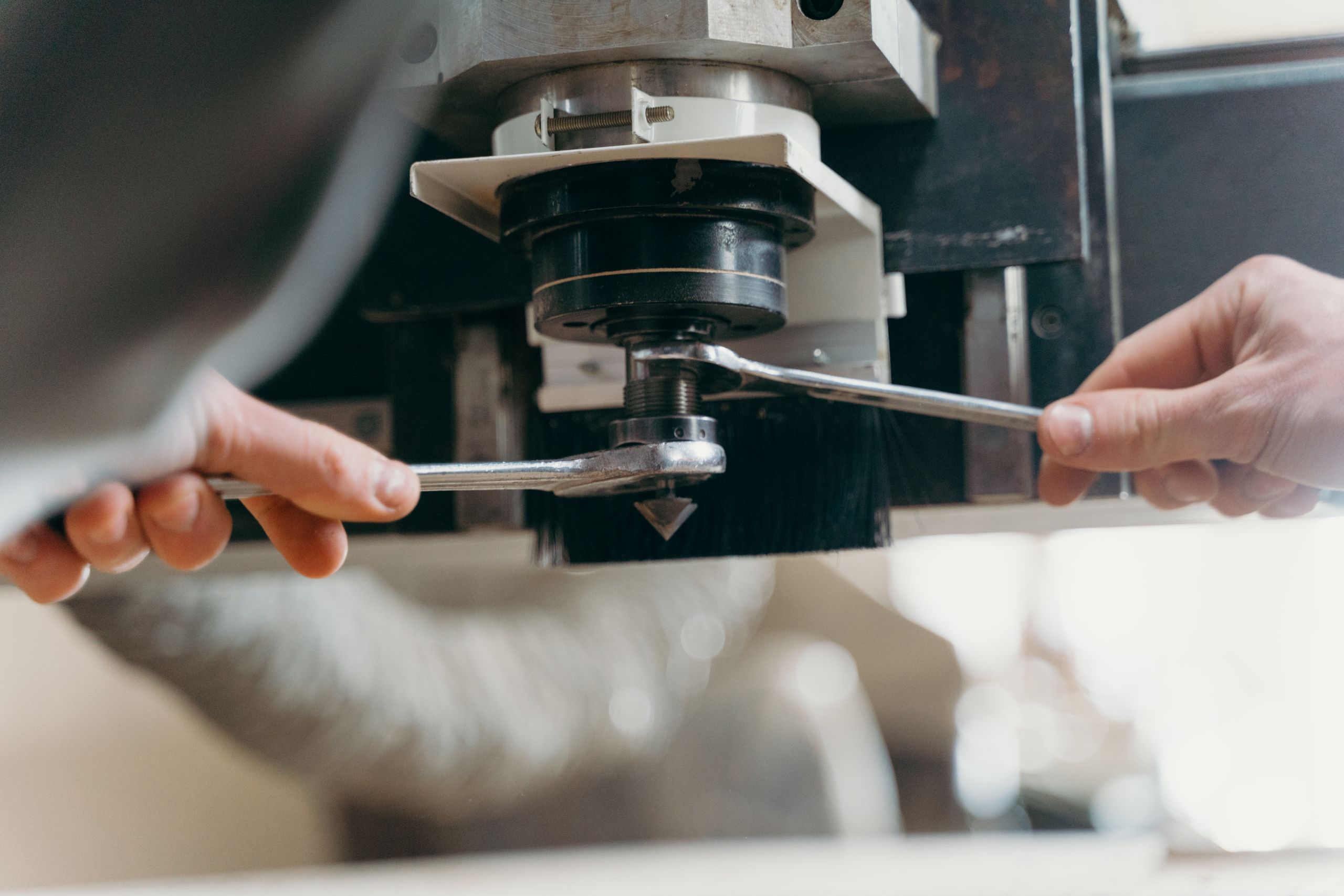
The PCD Combination Milling Cutter Setup depends on a clean, concentric interface. A particle trapped between contact surfaces can tilt the body and make one profile cut deeper. Use the specified arbor, sleeve, nut, spacer, or holder. Measure runout after final tightening and rotate the tool slowly by hand only when the machine is safely isolated.
Establish the tool datum
Choose a documented axial reference face and radial reference diameter. Enter offsets from the approved tool drawing rather than estimating from the visible edge. For a multi-step profile, verify which section controls Z-zero and which diameter controls path compensation. Reconfirm offsets after tool service because sharpening can alter cutting-edge position.
Speed, feed, and simultaneous engagement
Use manufacturer data for the exact cutter, work material, and machine. Calculate feed from active teeth, spindle speed, and approved chip load, then consider how many profile zones cut simultaneously. Broad engagement increases power and bending load. If the complete profile cannot enter safely, use staged depth, a lead-in, or a pre-machined relief as permitted by the process design.
Chip and dust control
- Position extraction so chips leave every cutting zone.
- Avoid directing chips into the holder, guide, or finished surface.
- Use coolant or air only when approved for the cutter, material, and machine.
- Prevent resin or adhesive from building up behind the edge.
- Control composite and panel dust with appropriate enclosure and filtration.
Test-cut validation
- Use representative material, thickness, coating, and support.
- Run a conservative path with the approved rotation and entry.
- Observe sound, spindle load, vibration, chip flow, and temperature signs.
- Measure each width, step, radius, angle, and feature relationship.
- Inspect both faces for burrs, breakout, burning, or delamination.
- Adjust one variable at a time and record the result.
Common setup errors
| Symptom | Possible setup error | Check |
|---|---|---|
| Step depth incorrect | Wrong axial datum | Drawing reference and Z offset |
| Profile oversize | Runout or wrong radial compensation | Mounting, diameter, path offset |
| Chatter across all features | Low rigidity or excessive engagement | Holder, clamping, entry, feed |
| One feature wears first | Unequal load or poor chip flow | Profile engagement and extraction |
| Diamond chipping | Shock, foreign material, vibration | Entry, panel, runout, workholding |
| Burning or melting | Rubbing or packed chips | Edge condition, feed-to-speed ratio |
Production monitoring
Track cut length or part count, spindle load, feature dimensions, finish, burr size, and cleaning frequency. Trend data can reveal gradual wear before a PCD edge chips. Keep a unique tool ID linked to its drawing, setup sheet, service report, and successful program revision.
Cleaning and reconditioning
Use a cleaning method approved for the diamond joint and tool body. Do not scrape edges with hard objects. Qualified service should inspect and recondition PCD geometry before severe wear changes the profile. After service, update offsets, verify balance and runout, and repeat the test-cut procedure.
Safety checklist
- Never exceed the marked maximum RPM.
- Use guards and enclosure rated for the cutter diameter and speed.
- Do not run a tool with unknown identity, cracks, chips, or loose parts.
- Isolate the machine before touching, cleaning, or measuring the cutter.
- Use dust and respiratory controls appropriate to the work material.
- Keep personnel clear during the initial test run.
Follow OSHA machine-guarding guidance, the machine builder’s instructions, and the cutter supplier’s limits. Browse JeeFoo precision profile tools for related products.
Frequently asked questions
Where should runout be measured?
Measure at the reference specified by the tool supplier. A body surface, arbor, or cutting diameter may require a different method, so do not assume one location represents the entire tool.
Why must offsets be checked after sharpening?
Reconditioning can move the effective cutting edge and alter a diameter, step, or profile relationship. Updated offsets restore the intended part geometry.
What should a setup sheet record?
Record tool ID, drawing revision, holder, mounting components, runout, datum, offsets, RPM, feed, material, entry, extraction, inspection results, and service history.
Use this PCD Combination Milling Cutter Setup workflow every time the tool is installed, returned from service, or moved to a different machine or material.

发表回复
要发表评论,您必须先登录。