
An aluminum substrate milling cutter is a high-chip-clearance routing tool designed for slotting, profiling, and separating aluminum-backed circuit boards, copper-clad laminates, IC carrier plates, and other ductile layered materials. This Aluminum Substrate Milling Cutter Guide compares fishtail and drill-point styles, explains geometry and setup, and shows how to reduce burrs, heat, chip packing, and edge damage.
What is an aluminum substrate milling cutter?
The Aluminum Substrate Milling Cutter Guide covers small-diameter rotary tools engineered for abrasive, layered, and heat-conductive board materials. A large chip-removal groove helps evacuate ductile aluminum or copper chips before they smear, weld to the edge, or scratch the finished wall. Geometry must balance a sharp cut with enough core strength for routing narrow slots and outlines.
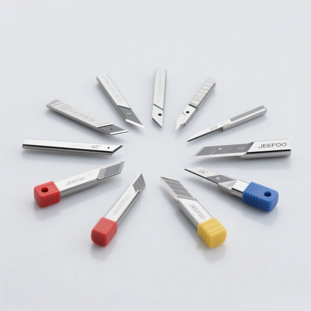
Aluminum Substrate Milling Cutter Guide: 9 key rules
- Identify the stack: record aluminum thickness, copper foil, dielectric, solder mask, laminate, and coating.
- Choose the entry style: use fishtail geometry for clean through-routing and drill-point geometry when controlled entry is required.
- Match diameter to slot width: allow for tool runout, wear, and the required dimensional tolerance.
- Keep overhang short: small cutters deflect quickly when flute length or projection is excessive.
- Prioritize chip space: wide polished flutes help move ductile chips away from the edge.
- Control heat: select feed, speed, engagement, and extraction that create chips instead of rubbing.
- Support the panel: stable backing and vacuum or mechanical clamping reduce vibration and breakout.
- Plan entry and exit: leads, ramps, tabs, and finishing passes affect burr direction and edge quality.
- Inspect frequently: fine tools may lose edge quality before visible breakage occurs.
Fishtail vs drill-point cutters
| Feature | Fishtail style | Drill-point style |
|---|---|---|
| Tip form | Opposing end lips with center relief | Pointed center-cutting end |
| Typical strength | Clean edge control in through-routing | Controlled entry and plunge capability |
| Best use | Profiling, outlines, separation, slots | Entry, pilot features, slot initiation |
| Bottom surface | May leave a characteristic center form | Produces a pointed entry geometry |
| Selection check | Panel support and breakout direction | Point strength and plunging load |
Compatible board materials
- Aluminum substrate and metal-core PCB panels
- Copper-clad and high-ductility metal laminates
- PBGA, BOC, CSP, and IC carrier-board slot forming
- Composite circuit-board stacks approved for the cutter geometry
- Thin nonferrous sheets where burr control and chip evacuation are critical
For the Aluminum Substrate Milling Cutter Guide, material names alone are insufficient. Confirm the actual alloy, layer thickness, adhesive or resin system, abrasive fillers, surface coating, and panel construction. A cutter successful in one aluminum-backed board may behave differently in another stack.
Choose diameter, flute length, and shank
The Aluminum Substrate Milling Cutter Guide favors the largest diameter that fits the slot or contour because rigidity rises rapidly with diameter. Cutting-edge length should clear the full panel stack without unnecessary excess. Use a shank and collet combination that minimizes runout, and keep the cutting section as close to the holder as safe clearance permits.
Feed, speed, and chip formation
Start from manufacturer data for the exact diameter and board stack. Program feed from spindle speed, flute count, and recommended chip load, then reduce for deep slots or high engagement if required. Chips should evacuate cleanly; powder, smearing, discoloration, or built-up material indicates rubbing, recutting, heat, or a worn edge.
Toolpath strategy
- Use a lead-in that avoids shocking the fine tip.
- Ramp or enter through a suitable pilot when direct plunging is not approved.
- Control radial engagement in pockets and narrow channels.
- Leave a small finishing allowance when roughing load may deflect the cutter.
- Choose cutting direction after testing burr location and laminate breakout.
- Add tabs or suitable panel support for final separation.
- Keep the path clear of clamps, pins, and backing fixtures.
Burr and heat control
The Aluminum Substrate Milling Cutter Guide relies on sharp edges that shear ductile layers before they fold into a burr. Good extraction prevents chips from being dragged through the cut. A stable feed-to-speed relationship limits rubbing, while rigid support prevents the thin panel from vibrating. If burrs rise primarily on one side, test cut direction, support, edge condition, and finishing allowance before making a broad parameter change.
Setup checklist
- Verify tool model, diameter, flute length, entry style, and rotation.
- Clean the collet, holder, and shank; measure runout when tolerance requires it.
- Confirm panel flatness, backing condition, clamping, and vacuum support.
- Inspect the route for metal fixtures and conductive debris.
- Set extraction for chips and fine board dust.
- Confirm safe spindle speed and machine acceleration for the small cutter.
- Run a coupon test and inspect both wall and burr direction.
Troubleshooting
| Problem | Likely cause | Corrective check |
|---|---|---|
| Large aluminum burr | Dull edge, wrong direction, poor support | Inspect tool, reverse test direction, improve backing |
| Chip welding | Heat, rubbing, poor evacuation | Correct feed-to-speed ratio and extraction |
| Broken tip | Runout, shock entry, excessive engagement | Measure holder, change entry, reduce load |
| Stained wall | Recutting or built-up edge | Improve flute clearing and replace worn tool |
| Oversize slot | Runout, deflection, wrong offset | Measure tool, shank, holder, and path compensation |
| Layer breakout | Low support or unsuitable geometry | Test cutter style, direction, and backing |
Inspection and tool life
Inspect the tip and cutting edge under magnification, not only after a quality failure. Track route length, board stack, spindle load, burr size, slot width, and wall appearance. Replace the cutter when the process trend reaches a defined limit. Predictable replacement protects boards and reduces sudden tip failure.
Safety and dust control
Use enclosure, guarding, and extraction appropriate to metal chips and circuit-board dust. Conductive debris can create electrical hazards inside equipment. Follow OSHA machine-guarding guidance and the machine builder’s instructions. For related products, visit JeeFoo precision routing tools.
Frequently asked questions
Why does the cutter need a large chip groove?
Aluminum and copper layers create ductile chips that can smear or weld to the edge. Large flute space helps evacuate them and reduces recutting heat.
Which style is better for through-routing?
A fishtail style is commonly used for clean through-routing, while a drill-point style supports controlled entry. The correct choice depends on panel support, entry path, and required edge.
How can tool life be made predictable?
Control runout, heat, engagement, chip evacuation, and entry shock; then track route length and burr or dimensional trends for each board stack.
Use this Aluminum Substrate Milling Cutter Guide to connect the board stack, tool style, diameter, flute length, path, parameters, inspection, and replacement rule.

发表回复
要发表评论,您必须先登录。