
Visible milling lines are usually caused by tool runout, spindle tram error, worn or unequal inserts, tool deflection, vibration, incorrect feed and speed, poor workholding, chip recutting, thermal change, or an unsuitable finishing path. This Milling Cutter Lines Causes guide shows how to identify the pattern, isolate the source, and restore a smoother machined face.
What do milling cutter lines reveal?
For Milling Cutter Lines Causes, tool marks are diagnostic evidence. Evenly spaced feed marks may be normal for the selected feed per tooth, but deep ridges, repeating bands, crosshatch, steps between passes, or random scratches indicate a setup, tool, machine, or process problem. First record the direction, spacing, depth, and repeatability of the lines.
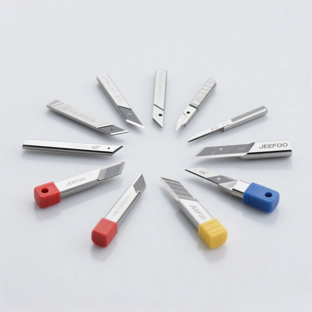
Milling Cutter Lines Causes: 10 common sources
- Spindle or tool runout: one edge cuts more than the others and leaves a repeating dominant mark.
- Spindle tram error: the cutter axis is not square to the surface, producing ridges or a crosshatch pattern.
- Unequal insert height: one face-mill insert protrudes farther and carries most of the finishing load.
- Worn, chipped, or built-up edges: damaged edges rub, tear, or scratch instead of shearing cleanly.
- Tool deflection: a long or slender cutter bends under load and changes its path.
- Chatter and vibration: unstable cutting creates periodic waves or bands.
- Incorrect feed and speed: excessive feed enlarges scallops, while rubbing can smear or work-harden the surface.
- Poor workholding: the workpiece shifts or vibrates as cutting forces change.
- Chip recutting: trapped chips are dragged across the finished face and leave random scratches.
- Thermal and machine errors: spindle growth, backlash, axis misalignment, or worn guides create steps and drift.
Identify the pattern before changing settings
| Surface pattern | Likely source | First check |
|---|---|---|
| Regular feed marks | Feed per tooth or tool geometry | Compare spacing with programmed feed |
| One deep repeating line | Runout or high insert | Measure edge height and radial runout |
| Crosshatch or dished face | Spindle tram error | Sweep the table with an indicator |
| Periodic waves | Chatter | Check rigidity, overhang, engagement |
| Random scratches | Chip recutting | Improve air, coolant, or chip evacuation |
| Step between passes | Tram, deflection, or Z error | Check alignment and cutting load |
Measure runout and insert height
Clean the spindle taper, holder, collet, shank, and insert pockets before measuring. Use a suitable indicator to check holder and cutter runout. On an indexable face mill, compare every insert at the same reference position. A single high insert can generate most of the visible pattern even when all inserts are new.
Check spindle tram
Mount an indicator so it sweeps a circle across the table or a verified reference surface. Compare readings in the machine’s X and Y directions. Correct tram according to the machine builder’s procedure. A cutter that is not perpendicular may cut more heavily on one side and leave a ridge when adjacent passes overlap.
10 practical fixes
- Clean and reseat the holder, cutter, inserts, and workpiece.
- Replace chipped edges and remove built-up material safely.
- Measure runout instead of judging it by eye.
- Equalize insert seating and torque fasteners to specification.
- Correct spindle tram and verify machine alignment.
- Shorten tool overhang and improve fixture rigidity.
- Reduce radial or axial engagement if deflection is excessive.
- Adjust feed, speed, and finishing allowance using tool data.
- Improve coolant, air blast, extraction, or chip flow.
- Use a consistent finishing pass after roughing stress is removed.
Optimize the finishing pass
The Milling Cutter Lines Causes checklist starts with a stable finishing path, constant engagement, appropriate stock allowance, and consistent direction. Avoid forcing a worn roughing tool to produce the final face. For large areas, plan overlap so adjacent passes blend without excessive recutting. If the machine allows it, use a dedicated finishing tool and keep its successful parameters documented.
Material-specific clues
- Aluminum: built-up edge and chip welding can scratch or smear the face.
- Steel: chatter, edge wear, and thermal effects may dominate.
- Plastic: heat can melt chips and drag them across the surface.
- Wood and composites: grain tear-out, dust recutting, and tool sharpness affect the visible pattern.
Diagnostic checklist
- Photograph and measure the line spacing.
- Note whether marks repeat once per revolution or once per tooth.
- Inspect all cutting edges under magnification.
- Measure runout, insert height, and tram.
- Check holder overhang, workholding, and machine play.
- Review feed per tooth, surface speed, engagement, and coolant.
- Make one controlled change at a time and compare results.
Follow OSHA machine-guarding guidance during inspection and operation. Never touch or measure a rotating tool. For related tooling, visit JeeFoo precision milling tools.
Frequently asked questions
Are all milling lines a defect?
No. Every cutting process leaves a geometric pattern. The concern is whether roughness, ridges, waviness, or steps exceed the drawing, function, or cosmetic requirement.
Why does one insert leave a deeper line?
It may sit higher because of debris, pocket damage, incorrect seating, unequal torque, insert variation, or holder runout. Clean, inspect, and measure each edge.
Can lower feed remove cutter lines?
It may reduce feed marks, but excessively low feed can cause rubbing. Correct runout, wear, alignment, vibration, and chip evacuation before relying on feed reduction.
Use this Milling Cutter Lines Causes workflow to diagnose evidence in order: pattern, tool, alignment, rigidity, parameters, chip flow, and machine condition.

发表回复
要发表评论,您必须先登录。