
Straight Groove and Taper Router Bit Guide: a double-edge straight-groove bit is designed for parallel-sided slots, pockets, rabbets, and trimming, while a tapered straight or tapered engraving bit uses an angled body to reach deeper features with added support. Select between them by wall angle, bottom profile, minimum feature size, reach, workpiece material, machine rigidity, and required finish.
Table of Contents
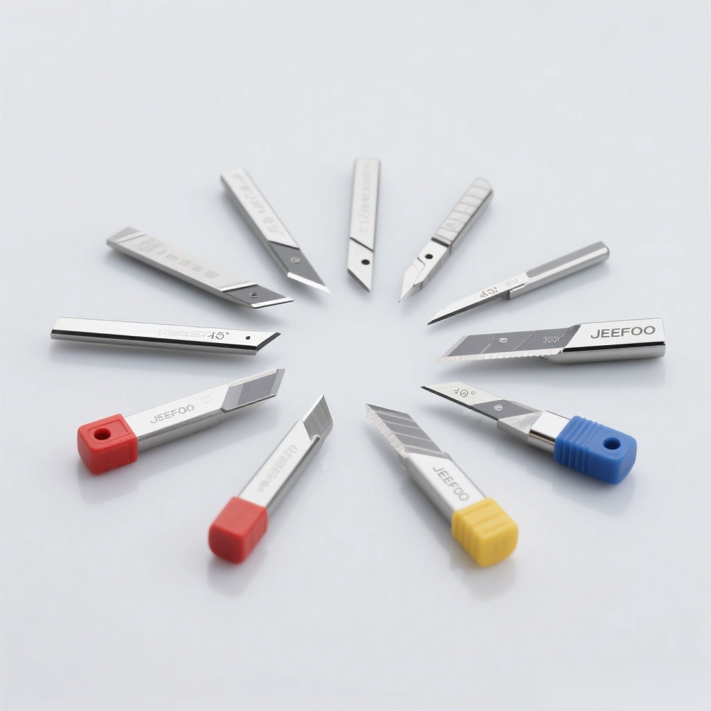
Straight Groove and Taper Router Bit Guide: Quick Answer
Use a double-edge straight-groove bit when the design requires parallel walls and a predictable slot width. Use a tapered cutter when the feature permits or requires angled walls, fine detail, or a longer reach with better body support. In both cases, match the shank and cutting material to the machine and workpiece, minimize projection and runout, and start with manufacturer-approved feed, speed, and engagement.
How the Two Cutter Types Differ
- Double-edge straight groove: two cutting edges, cylindrical cutting diameter, and parallel groove walls.
- Tapered straight cutter: angled body or cutting profile that creates draft or tapered walls and can improve stiffness toward the shank.
- Bottom geometry: may be flat, pointed, radiused, or non-center-cutting depending on the exact model.
- Entry capability: never assume either tool can plunge; confirm center-cutting geometry and supplier instructions.
Choose by Feature Geometry
The Straight Groove and Taper Router Bit Guide begins with the drawing. For a dado, straight slot, pocket, or parallel shoulder, the straight-groove design is usually the direct match. For tapered lettering, molds, relief work, angled channels, deep narrow details, or draft walls, a tapered tool may be appropriate. Model the real tip radius, included angle, cutting length, and maximum diameter in CAM.
Select Diameter, Angle, and Reach
Use the largest diameter that can access the smallest feature. On a tapered cutter, calculate the effective width at the programmed depth because width increases with depth. Choose a cutting length just beyond the required engagement and keep overall projection short. Excessive reach increases deflection, chatter, and breakage risk even when the shank is large.
Match Tool Material to the Workpiece
Solid carbide provides stiffness and wear resistance for many precision routing tasks, while carbide-tipped designs may be economical for selected larger woodworking cuts. Sharp polished geometries can help approved non-ferrous metals and plastics; specific coatings may improve life in suitable materials. Wood composites and fiber-reinforced materials can be abrasive and may require dedicated geometry, extraction, and exposure controls.
Flute Count and Chip Space
A two-edge straight bit shares the cut between two edges and can provide balanced cutting when runout is controlled. Tapered tools may have one or more flutes. More flutes can increase feed capacity but reduce chip space. The Straight Groove and Taper Router Bit Guide recommends choosing flute count from chip evacuation needs, machine speed, workpiece behavior, and supplier chip-load data.
Feed, Speed, and Engagement
Calculate feed from recommended chip load, flute count, and actual RPM. Full-width slots generate more heat and congestion than light side cuts. Small tapered tips are sensitive to overload, abrupt entry, and runout. Use conservative axial steps, controlled ramps or helices when approved, and separate roughing and finishing passes when the geometry and tolerance justify them.
Holder, Collet, and Runout
Clean the spindle, collet, nut, holder, and shank. Use the exact shank size and specified tightening torque. Clamp only the straight shank at adequate depth without bottoming it out. Measure assembled runout whenever possible. Unequal edge loading causes chatter, variable groove width, poor finish, edge chipping, and shortened tool life.
Toolpath and Cut Direction
Confirm the machine’s backlash, rigidity, and workholding before selecting climb or conventional cutting. Avoid sudden direction changes, sharp load spikes, and dwelling. For tapered engraving, surface flatness and Z calibration directly affect line width. Simulate the toolpath, include the real tool geometry, and test the smallest features on scrap material.
Chip Evacuation and Finish
Straight flutes may not lift chips as aggressively as an up-cut spiral, so extraction, air, or an approved fluid strategy must keep the cut clear. Recutting chips raises heat and damages the surface. For laminates or fragile top edges, compare straight, shear-angle, compression, down-cut, and up-cut designs for the actual material before production.
Troubleshooting Checklist
- Chatter: reduce projection, improve workholding, measure runout, and review engagement.
- Burning: inspect sharpness, chip load, RPM, evacuation, and dwelling.
- Wrong groove width: verify cutter diameter, tapered width at depth, runout, and Z calibration.
- Broken fine tip: check entry, sudden load, projection, material, and collision risk.
- Tear-out: review edge condition, grain direction, geometry, and cutting direction.
Inspection and Maintenance
Clean resin or residue with a method approved for the cutter, dry it, and store it in a protective holder. Inspect both straight edges or the tapered tip under adequate light and magnification. Replace or professionally sharpen the tool when it is chipped, cracked, bent, worn beyond limits, or unable to hold finish and dimensions after setup corrections.
Safety Rules
Keep guards closed, secure the workpiece, wear suitable PPE, and never clear chips by hand near a rotating cutter. Respect the lowest speed rating of the tool, holder, spindle, and machine. Review OSHA machine guarding guidance for general context, and visit JeeFoo Tools for related routing cutters.
Straight Groove and Taper Router Bit FAQ
Which bit makes parallel groove walls?
A cylindrical straight-groove bit is the direct choice when the design requires parallel walls, subject to tool deflection and machine accuracy.
Why use a tapered cutter?
It can create angled walls, reach fine details, and provide more body support toward the shank when the design permits a taper.
Can both cutter types plunge?
Only when the exact model is center-cutting and the manufacturer permits plunging. Otherwise use an approved ramp, helix, or predrilled entry.
How do I control tapered line width?
Follow the Straight Groove and Taper Router Bit Guide: use the real angle and tip size in CAM, flatten or probe the surface, calibrate Z, minimize runout, and control depth.
Final Selection Checklist
- Use the Straight Groove and Taper Router Bit Guide to confirm wall angle, bottom profile, and minimum feature.
- Use the Straight Groove and Taper Router Bit Guide to verify diameter, angle, reach, shank, material, and flute count.
- Use the Straight Groove and Taper Router Bit Guide to validate runout, toolpath, chip control, feed, speed, and safety.


发表回复
要发表评论,您必须先登录。