
Mini Word Milling Cutter Selection Guide: a mini word milling cutter is a small-diameter rotary tool used for detailed lettering, narrow grooves, fine contours, and compact features on CNC engraving or milling equipment. Reliable results depend on matching tip geometry, diameter, flute design, cutting length, substrate, coating, holder, and cutting data to the workpiece and feature size.
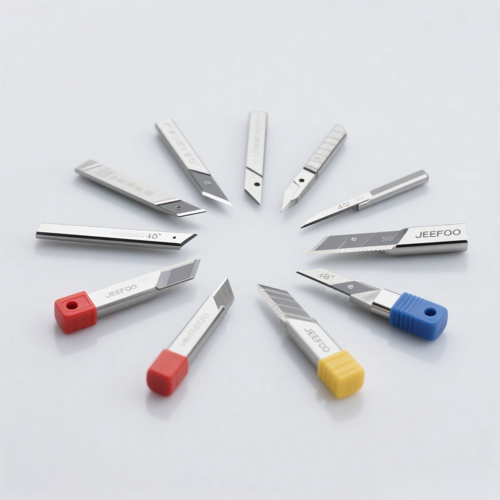
Mini Word Milling Cutter Selection Guide: Quick Answer
Select the largest diameter and shortest reach that can enter the lettering or detail, then choose a tip shape that matches the required line width and bottom profile. Confirm the cutter material for the workpiece, use a precision low-runout collet, start with the supplier’s chip-load and RPM data, and use shallow, stable passes with effective chip evacuation.
What Is a Mini Word Milling Cutter?
The term commonly describes a compact engraving or milling cutter intended for small characters and fine features. Designs may include flat-end micro mills, V-shaped engraving cutters, tapered cutters, ball or radius tips, and single- or multi-flute geometries. Because product naming varies, always select from the actual drawing, dimensions, allowable materials, and operating limits rather than the name alone.
Choose the Correct Tip Geometry
- Flat end: narrow slots, pockets, and flat-bottom features.
- V tip: variable-width lettering, chamfers, and line engraving.
- Ball or radius tip: smooth 3D details and rounded grooves.
- Tapered body: added stiffness for deep, fine features where the wall angle is acceptable.
- Single flute: larger chip space for selected plastics and non-ferrous work.
- Multiple flutes: more cutting edges and potential feed capacity when chip space remains adequate.
Diameter, Tip Size, and Reach
The Mini Word Milling Cutter Selection Guide favors the largest rigid geometry that still reproduces the smallest feature. Tip diameter or included angle determines the effective line width at a given depth. Excessive cutting length and projection reduce stiffness and amplify runout. Model the actual corner radius, draft angle, and minimum channel width in CAM before machining.
Match the Cutter to the Material
Solid carbide is common for small tools because it combines stiffness and wear resistance, but it can be brittle under impact or poor runout. Sharp polished geometries can help selected aluminum and plastics; suitable coated carbide may improve life in approved steels or abrasive materials. Composite machining can release hazardous dust and rapidly wear an unsuitable edge. Use the cutter manufacturer’s compatibility chart for every material.
Feed, Speed, and Chip Load
Calculate feed from recommended chip load, flute count, and measured spindle speed. A small cutter is sensitive to both overload and rubbing. Excessive feed, depth, runout, or sudden entry can break the tip; very low feed can create heat and rapid wear. The Mini Word Milling Cutter Selection Guide recommends conservative engagement, a controlled ramp or helical entry when approved, and a separate finishing pass when dimensional accuracy matters.
Control Runout and Tool Projection
Clean the spindle, nut, collet, and shank before assembly. Use the exact shank size, adequate gripping depth, and the specified tightening torque. Do not clamp on the flute or transition radius. Measure the assembled tool when possible: even modest runout can cause one flute to carry most of the load and can make a delicate cutter fail before the programmed chip load is reached.
Toolpath and Entry Strategy
Use a toolpath that avoids abrupt direction changes, full-width overload, and unsupported thin features. Confirm whether the cutter is center-cutting before plunging. For V engraving, control depth carefully because line width changes with depth. For tiny text, simulate the toolpath, verify character spacing, and test on scrap material before machining the final part.
Chip Evacuation, Cooling, and Dust
Re-cut chips increase heat and edge damage. Use extraction, air, mist, or coolant only when the machine, cutter, workpiece, and facility permit it. Plastics may melt if heat accumulates. Wood and composite dust may require dedicated collection and respiratory controls. Never direct loose chips or dust toward people, electrical equipment, or unprotected machine components.
Troubleshooting Fine Lettering
- Broken tip: inspect runout, entry, engagement, tool projection, and collisions.
- Fuzzy edges: verify sharpness, workholding, grain direction, and geometry.
- Melted plastic: improve chip evacuation and correct feed, RPM, and edge condition.
- Uneven line width: check surface flatness, Z calibration, runout, and V-tip depth.
- Missing detail: compare the minimum feature with actual cutter geometry and CAM tolerance.
Inspection and Replacement
Inspect the tip under magnification before precision work. Replace the tool when it is chipped, cracked, bent, heavily worn, or no longer produces a stable finish after setup corrections. Store small cutters separately in protective holders, label their dimensions, and record material, runtime, and failure mode so future selections are based on evidence.
Safety Rules
Keep guards closed, secure the workpiece, wear suitable eye and hearing protection, and never touch or clear chips near a rotating cutter. Respect the lowest speed rating of the tool, holder, spindle, and machine. Review OSHA machine guarding guidance for general context, and visit JeeFoo Tools for related cutters.
Mini Word Milling Cutter FAQ
Which cutter is best for tiny letters?
Use the largest rigid tip that can reproduce the smallest line and corner, with geometry chosen for the required flat, V-shaped, rounded, or tapered profile.
Why do small cutters break easily?
Common causes are excessive runout, long projection, aggressive engagement, incorrect entry, recutting chips, workpiece movement, or a collision.
Can one tool cut every material?
No. Edge geometry, carbide grade, coating, flute space, and cutting data must suit the specific material and machine.
How can I keep lettering width consistent?
Follow the Mini Word Milling Cutter Selection Guide: flatten or probe the surface, calibrate Z, control V-tip depth, minimize runout, secure the workpiece, and use a stable finishing pass.
Final Selection Checklist
- Use the Mini Word Milling Cutter Selection Guide to confirm feature geometry and minimum line width.
- Use the Mini Word Milling Cutter Selection Guide to verify material compatibility, tip size, reach, shank, and flute design.
- Use the Mini Word Milling Cutter Selection Guide to validate runout, toolpath, chip control, feed, speed, and safety.


发表回复
要发表评论,您必须先登录。