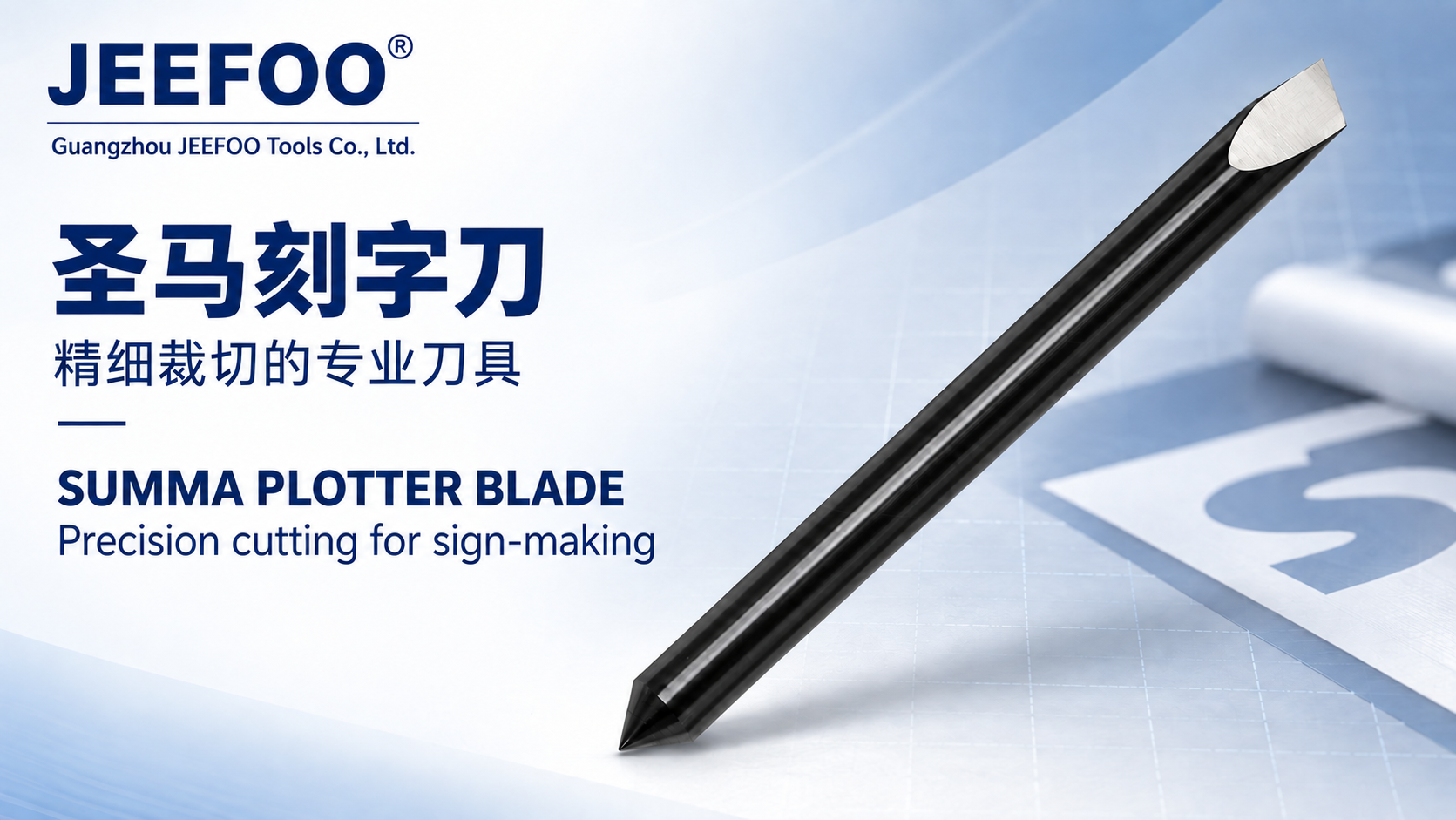
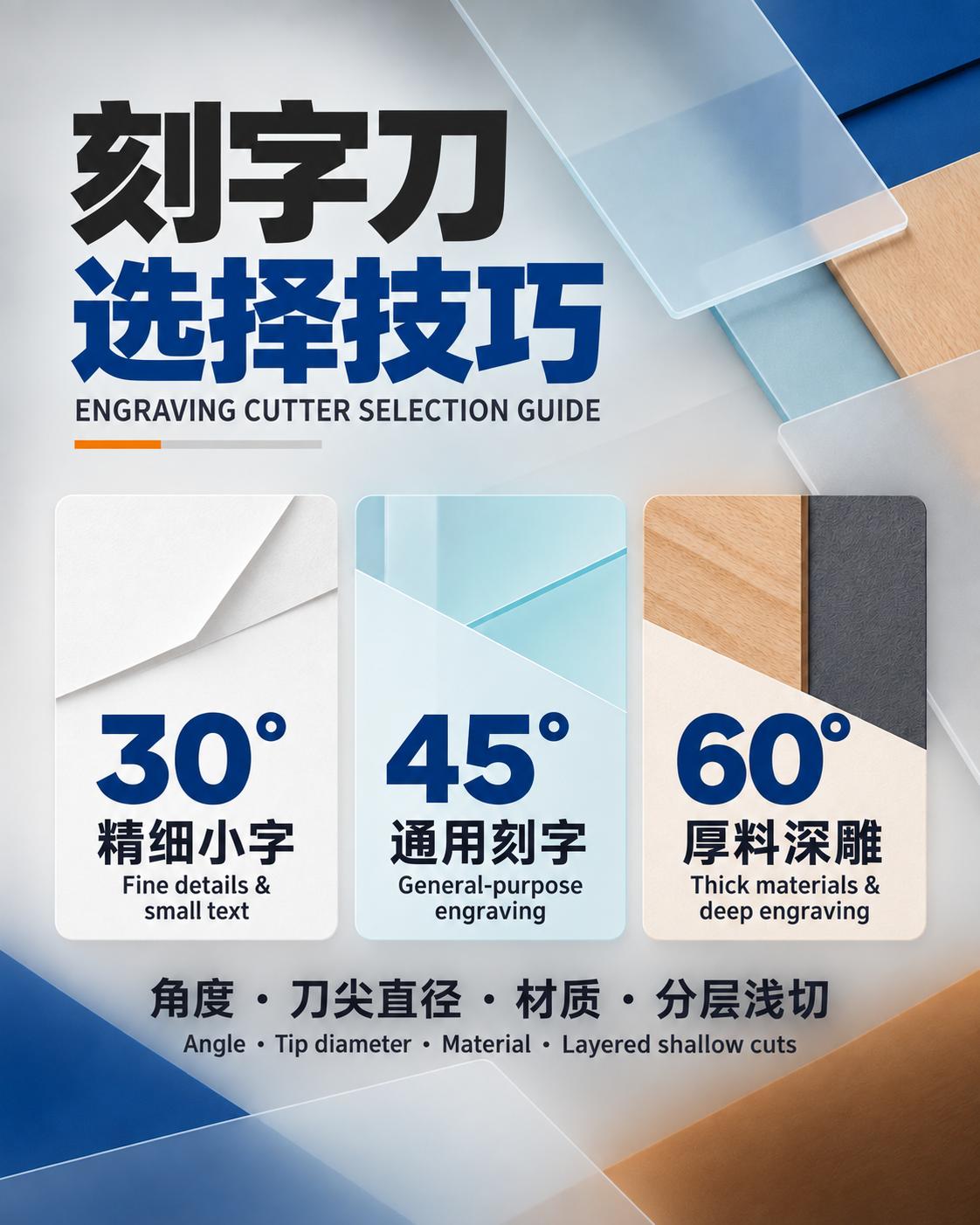
3DV Carving Tool Setup Guide: a 3DV carving tool is a V-shaped or tapered engraving cutter used to create detailed lettering, reliefs, chamfers, tapered grooves, and three-dimensional surface features. Accurate results require the real tip size and included angle in CAM, minimal runout and projection, controlled depth, suitable step-over, a stable workpiece, and cutting data matched to the material.

3DV Carving Tool Setup Guide: Quick Answer
Measure or verify the actual tip diameter, included angle, cutting length, shank, and maximum diameter; enter those values in the CAM tool library; keep the holder clean and runout low; flatten or probe the work surface; use shallow engagement and a small finishing step-over; then validate line width, depth, finish, and detail on scrap material.
1. Identify the Exact 3DV Geometry
Supplier names are not standardized. A 3DV cutter may have a pointed, truncated, radiused, ball, or flat tip and may be straight or tapered. Record included angle, half angle, tip diameter or radius, maximum cutting diameter, flute count, cutting length, taper length, shank diameter, and overall length from the drawing.
2. Understand Width Changes with Depth
For a V-shaped tool, the cut becomes wider as depth increases. A small Z error can visibly change lettering stroke width. The 3DV Carving Tool Setup Guide recommends calculating effective width from the actual tip and angle, then confirming it with a test groove. Do not assume a nominally sharp tip has zero diameter.
3. Match the Cutter to the Material
Sharp polished carbide may suit approved woods, plastics, foams, and non-ferrous materials; specific coatings and edge preparations may suit other workpieces. Composite, stone, or abrasive materials can require dedicated diamond or carbide grades and dust controls. Use the cutter manufacturer’s compatibility chart and never extrapolate one material’s settings to another.
4. Build an Accurate CAM Tool Model
Enter the actual tip form, angle, diameter, flute length, taper, shank, holder, stick-out, and collision envelope. Use a tool number and description that uniquely identify the physical cutter. Simulate roughing, finishing, retracts, holder clearance, and the smallest detail. Keep the tool library revision with the NC program.
5. Minimize Runout and Projection
Clean the spindle, holder, collet, nut, and shank. Use the exact shank size and specified torque. Clamp only the straight shank at adequate depth and keep projection as short as the model permits. Runout moves the tip off-axis, causing unequal edge loading, variable width, chatter, broken tips, and lost detail.
6. Flatten or Probe the Work Surface
Because V-cut width depends on depth, surface flatness and Z reference are critical. Surface the spoilboard or fixture where appropriate, secure the workpiece without bowing, and probe or map the surface when the machine and CAM workflow support compensation. Confirm the programmed zero after tool measurement and before the final piece.
7. Choose Roughing and Finishing Strategies
Remove bulk material with a stronger roughing tool when possible, leaving a controlled allowance for the 3DV cutter. Use parallel, radial, contour, pencil, or rest-finishing paths according to surface shape. Keep engagement consistent, avoid burying a fine tip, and select a finishing step-over based on cusp height and required texture.
8. Set Feed, Speed, and Entry
Calculate feed from manufacturer chip-load data, effective edge count, and actual RPM. Small tips are sensitive to both overload and rubbing. Confirm center-cutting capability before plunging; otherwise use an approved ramp, helix, or pre-cleared entry. Reduce axial depth for long reach, fragile detail, hard spots, and weak workholding.
9. Control Chips, Dust, and Heat
Use extraction, air, mist, or coolant only when approved for the machine, material, and tool. Fine 3D paths can recut chips and accumulate heat. Plastics may melt, wood can burn, and composites may release hazardous dust. The 3DV Carving Tool Setup Guide recommends directing chip control into the active cut and monitoring edge buildup.
Troubleshooting 3DV Carving
- Line width varies: inspect surface flatness, Z zero, tip geometry, runout, and tool deflection.
- Broken tip: review entry, engagement, projection, runout, collision, and material compatibility.
- Visible scallops: reduce finishing step-over or use a more suitable tip radius.
- Lost fine detail: compare minimum feature size with the actual tip and CAM tolerance.
- Burning or melting: correct chip load, RPM, sharpness, evacuation, and dwelling.
Inspection and Replacement
Inspect the tip under magnification before precision work and after unexpected load or sound. Replace a chipped, cracked, bent, worn, or contaminated cutter when cleaning and setup correction do not restore results. Record tool life, material, program, step-over, finish, dimensions, and failure mode.
Safety Rules
Secure the workpiece, close guards, wear suitable PPE, remove setup tools, and never clear chips near a rotating cutter. Respect the lowest speed rating of the tool, holder, spindle, and machine. Review OSHA machine guarding guidance for general context, and visit JeeFoo Tools for related carving cutters.
3DV Carving Tool FAQ
Why does V-carved text change width?
Width changes with depth, so surface flatness, Z zero, tip diameter, included angle, runout, and deflection all matter.
Should I rough with the 3DV tool?
Often a stronger tool should remove bulk material first, leaving a controlled allowance for the detailed finishing cutter.
How do I reduce visible scallops?
Use an appropriate tip radius, reduce step-over, keep engagement consistent, and ensure the machine and holder are rigid.
How can I improve repeatability?
Follow the 3DV Carving Tool Setup Guide and document tool geometry, projection, runout, surface mapping, paths, parameters, and inspection results.
Final Setup Checklist
- Use the 3DV Carving Tool Setup Guide to verify tip, angle, taper, shank, and material.
- Use the 3DV Carving Tool Setup Guide to control CAM geometry, Z reference, runout, paths, and step-over.
- Use the 3DV Carving Tool Setup Guide to validate cutting data, chip control, inspection, and safety.