A carbide 3D carving tool is selected by tip shape, radius, taper, diameter, reach, material, detail size, and surface-finish target. It is commonly used for relief carving, corner cleaning, chamfering, molds, signs, sculptures, and complex contours in wood, plastic, foam, composites, and nonferrous materials.
What is a carbide 3D carving tool?
Table of Contents
The tool is ground from cemented carbide for rigidity, sharpness, and wear resistance. Common profiles include ball nose, tapered ball nose, V-bit, conical, and small flat-end cutters. The correct profile follows the 3D model while controlling cusp height, corner detail, deflection, and cutting force.
Carbide 3D Carving Tool Guide: 9 tips
- Define the 3D feature: identify relief, corner cleanup, chamfer, deep cavity, mold, or fine engraving.
- Choose tip profile: ball nose suits contours, V-bits suit lines, and flat ends suit small floors.
- Match the material: select edge polish, coating, flute count, and rake for the workpiece.
- Select tip radius: smaller radii capture detail but are more fragile.
- Use taper for support: tapered tools strengthen a small tip during deep carving.
- Limit reach: use the shortest flute and projection that clears the model.
- Control step-over: smaller step-over reduces cusp height and improves finish.
- Plan roughing first: remove bulk material with a stronger tool and leave uniform stock.
- Inspect test areas: verify detail, finish, dimensions, chips, sound, and edge wear.
Ball nose versus tapered ball nose
A straight ball nose cutter follows curved surfaces and is easy to program, but small diameters can deflect during deep work. A tapered ball nose retains a fine spherical tip while the tapered body adds stiffness. It is well suited to deep reliefs, sculptures, mold details, and long-reach carving.
V-bits and corner-cleaning cutters
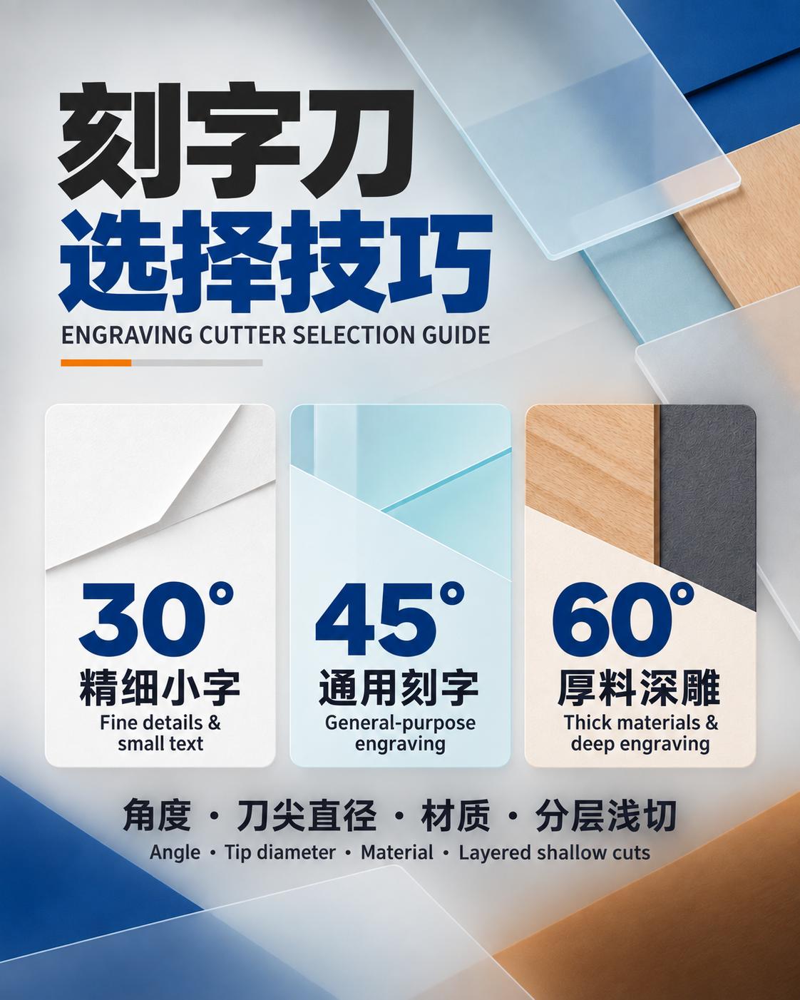
V-bits produce lettering, sharp lines, chamfers, and variable-width grooves. Narrow angles reach tight details; wider angles create broader cuts at shallow depth. Corner-cleaning tools remove residual stock left by larger roughers. Confirm tip diameter, included angle, and toolpath assumptions before cutting.
Choose tool size and reach
Use the largest tip that captures the required detail because larger tools are stiffer and faster. Select cutting length only slightly beyond the required depth. Check shank and holder clearance against the model, especially on steep walls and recessed features. Simulate the full holder, not only the cutting edge.
Roughing, semi-finishing, and finishing
Rough with a larger flat or radius tool using stable engagement. Leave a uniform allowance for semi-finishing, which reduces stock variation before the final pass. Finish with the selected ball, taper, or V-profile using a step-over that meets cusp-height and time requirements.
Set speed, feed, and step-over
Begin with toolmaker chip-load and surface-speed data. Adjust for the tool’s effective cutting diameter, especially on ball nose tools where speed approaches zero at the center. Use sufficient feed to form chips, lower engagement for long reach, and set step-over from required finish rather than habit.
Toolpath and grain-direction planning
Use smooth entries, constant engagement for roughing, and consistent finishing directions. Raster, offset, spiral, and waterline paths leave different textures. In wood, grain direction affects tear-out; in plastic, evacuation affects melting; in metal, rigidity and lubrication influence finish and tool life.
Troubleshooting common defects
- Visible cusps: reduce step-over or use a larger effective radius.
- Broken fine tip: reduce runout, stock, impact, or projection.
- Fuzzy wood detail: use a sharper edge, revise direction, and add a light finish pass.
- Melted plastic: improve chip load, evacuation, and cooling.
- Uneven finish: stabilize remaining stock, tool direction, runout, and feed.
Inspection and safety checklist
Inspect the tip under magnification, clean the holder, measure runout, secure the workpiece, verify offsets, and simulate holder clearance. Follow machine and cutter guidance. Review the OSHA machine guarding guidance and explore JeeFoo carving and cutting tools.

Frequently asked questions
Which tool is best for 3D relief carving?
A ball nose or tapered ball nose cutter is the common finishing choice. Select tip radius and taper from detail size, depth, reach, and machine rigidity.
How does step-over affect finish?
Smaller step-over reduces cusp height and creates a smoother surface but increases cycle time. Balance it against tool radius and required post-processing.
Why use a tapered carving tool?
The tapered body supports a small cutting tip, reducing deflection during deep or long-reach carving while preserving fine detail.