Plotter blade clearance is the physical gap between a raised cutting tip and the media surface during a move that should leave no cut. When a fine mark appears between otherwise clean shapes, the blank area deserves attention. The useful question is what the edge was doing when that mark formed. Its location and timing can be more informative than immediately choosing another blade.
Plotter blade clearance changes when a sheet rises
Imagine two separate letters on a sheet. Their outlines cut correctly, yet an unwanted mark crosses the space between them. If the tool travels through that space while raised, the intended cutting contours explain only part of the result. The edge also needs to pass over the material without touching it.
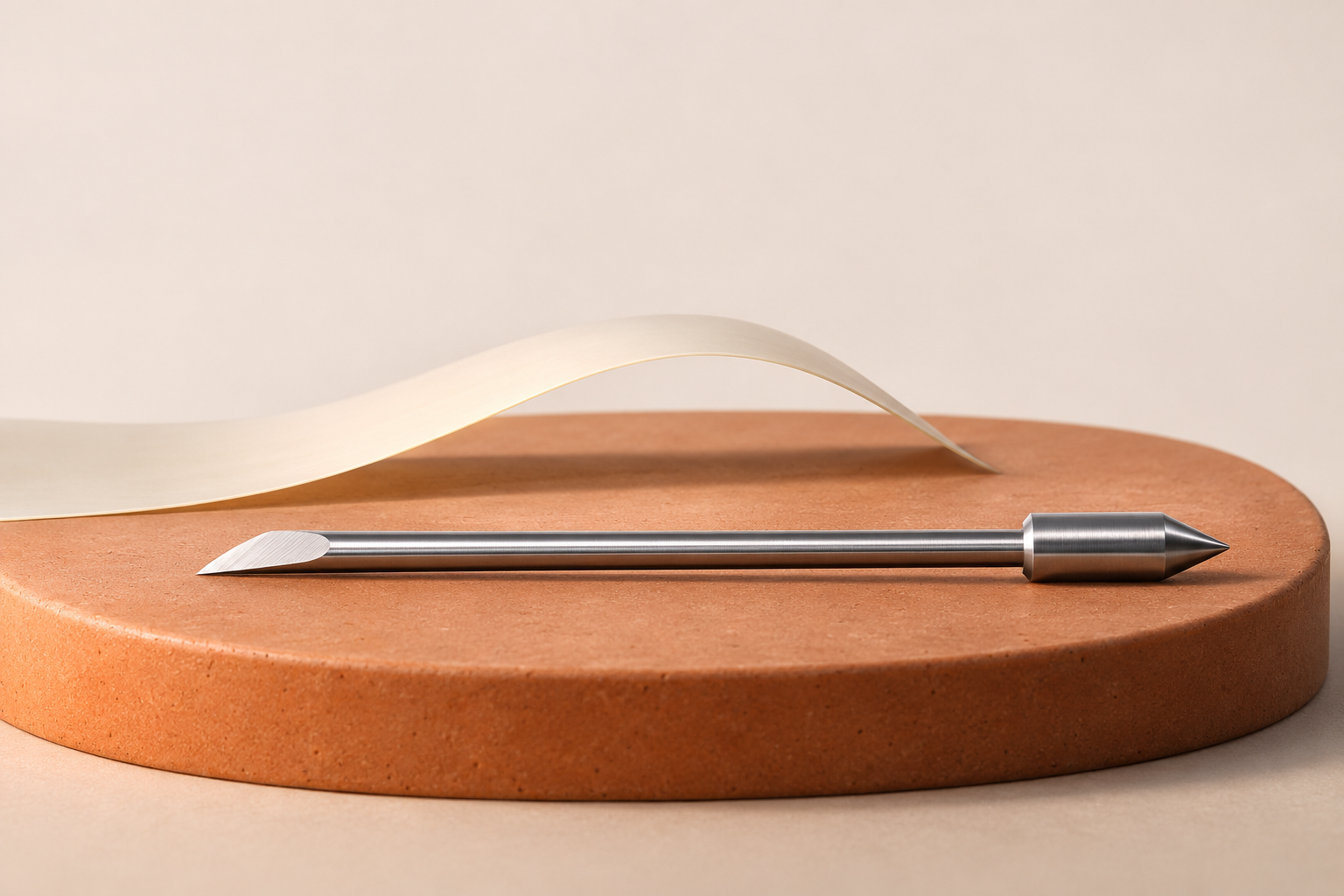
There are two sides to that gap: the position of the tip and the local height of the sheet. In a simple geometric picture, a sheet that rises toward an unchanged tip reduces the available space. This explains why an acceptable contour cut does not, by itself, establish clearance everywhere along a later travel move. It is an explanation of the geometry, not proof that a particular scratch came from lifted media.
Travel speed and lift height describe different things
The Roland BN2 User’s Manual, page 166, defines Rise Movement Speed as the speed of travel from one cutting line to the next. It advises reducing that speed if media comes loose during no-load feed and the blade damages its surface. This is model-specific guidance for a stated condition. The setting describes travel speed; it should not be read as a command to increase the blade’s lifting height.
Menu wording can be misleading without its definition. Graphtec’s FCX2000 revision history records a change from TOOL UP SPEED to MOVING SPEED in version 2.30, alongside a separate tool-down-speed setting. The naming example reinforces a reading habit: identify which motion a control governs before treating it as a remedy.
Blade projection has more than one limit
A blade that projects farther from its holder changes the physical position of its tip. Mimaki’s APC-130 support guidance warns that excessive extension can cause unintended contact with media and cutting in areas that should remain uncut. This supports considering projection when investigating stray contact. It does not supply a universal extension value for other holders.
Shortening the projection as much as possible is not a complete solution either. In its separate BY-20 blade-extension instructions, Roland warns that too little extension can bring the holder cap against a printed surface and damage it. That warning concerns the holder’s contact geometry, not a diagnosis of raised-travel scratches. Together, these examples show why the complete blade-and-holder arrangement needs its own documented adjustment procedure.
An unwanted line does not identify its own cause
A surface scratch between shapes and an unintended cutting stroke can look similar in a photograph. SignCut’s official guidance on diagonal cuts discusses communication and memory-buffer issues as possible sources of random cutting. A line across open space therefore does not establish a clearance problem on its own.
A useful description connects the mark to an event: did it appear while the tool was relocating, while a contour was being cut, or at another point in the job? Compare the affected area with the intended artwork and preserve the sample. Observe only from a safe position with the machine’s safeguards in place; stop according to its instructions before inspecting or handling the assembly. Avoid reaching toward a moving blade to find the contact point.
Keep the actual blade in the explanation
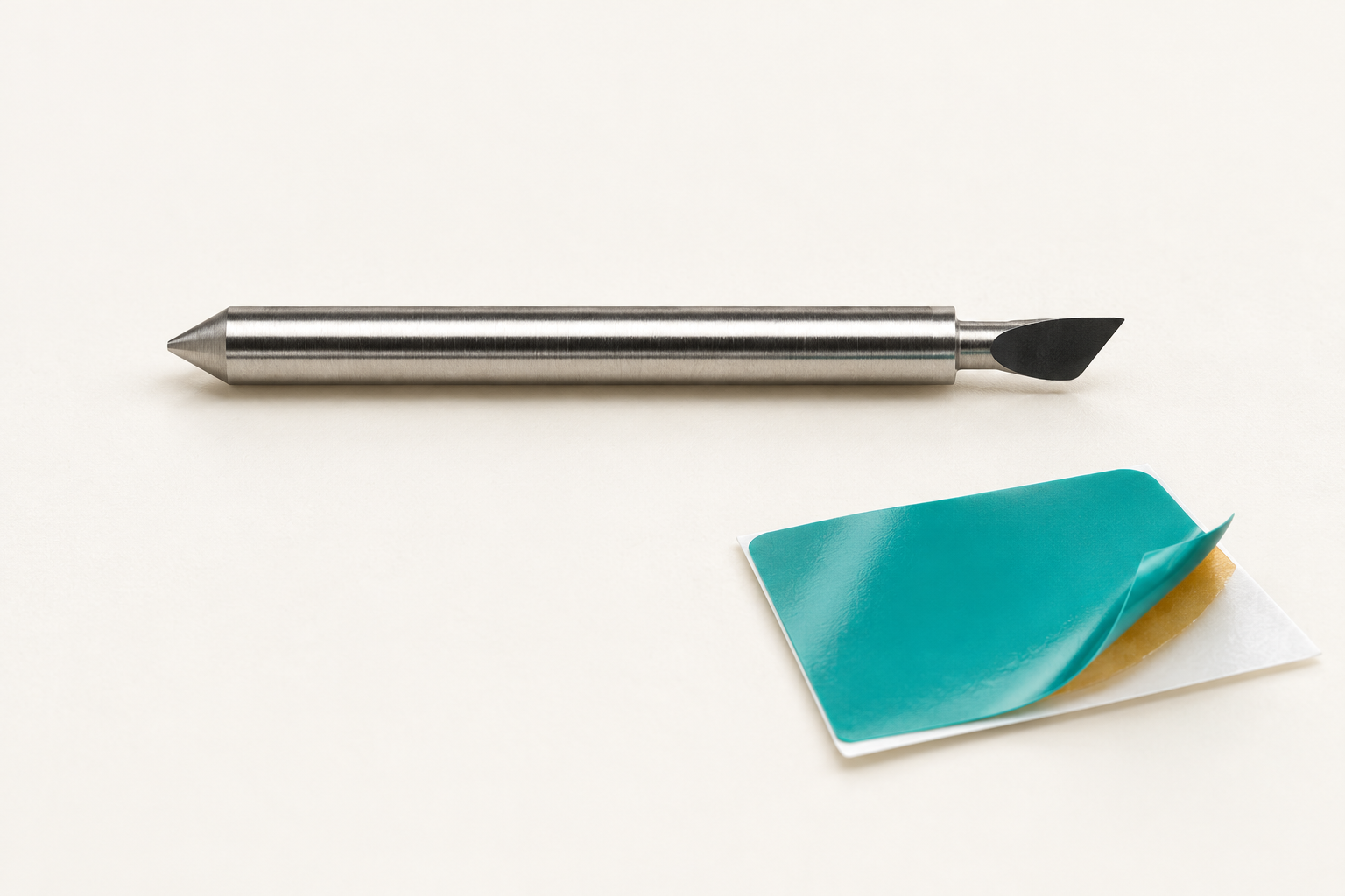
The slender blade used as the visual reference for this article comes from JEEFOO’s Graphtec-family catalogue listing. Its photograph supports identifying the visible tool form, not measuring projection or confirming a machine installation. The different manufacturer references above explain particular mechanisms and terminology; they do not establish compatibility between this catalogue item and those machines.
Plotter blade clearance belongs in the assessment of the finished sheet alongside the intended contours. A good explanation accounts for both the edges that were meant to cut and the spaces that were meant to remain untouched.